AX501最新3.6x版英文操作手册.pdf.pdf - 第15页
4022 593 51894 Operatin g Man ual 09.01 AX-301/501, AX-3/5 15 2 2.4 Pick and place module , o v erview Figure 12 Pick and place modu le , overview 1 Compact placem ent r obot, see 2.4.1. Robots. 2 Stan dard pla cemen t r…
4022 593 51894 Operating Manual
09.01 AX-301/501, AX-3/5 15
2
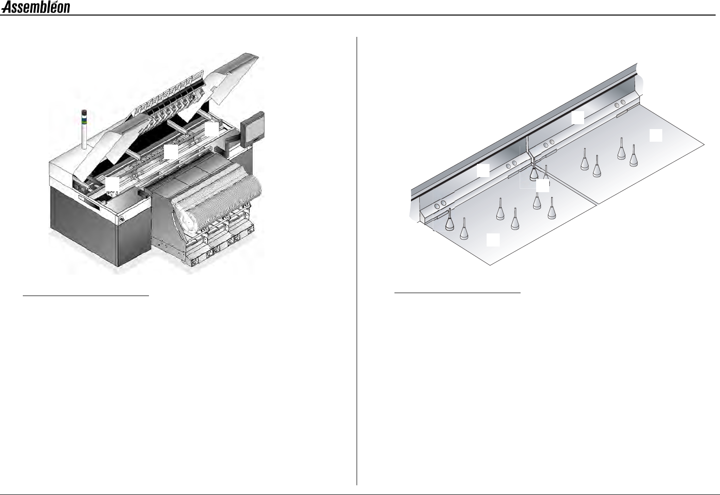
2.4 Pick and place module, overview
Figure 12 Pick and place module, overview
1 Compact placement robot, see 2.4.1. Robots.
2 Standard placement robot, see 2.4.1. Robots.
3 Placement head, see 2.4.2. Placement head.
4 Toolbit exchange unit, see 2.4.3. Toolbit exchange unit.
5 CV camera, see 2.4.4. CV camera.
2.4.1 Robots
LED status indicators on the handle:
Green = Running, Red = Attention!
Both compact placement robots (1) as well as standard placement robots
(2) can be found on the machine. Functionally they are the same, but the
width of a compact placement robot is half the width of a standard
placement robot. This way the output can be doubled without increasing
the area occupied by robots. The robot (1, 2) moves the placement head
(3) to the correct pick and place locations.
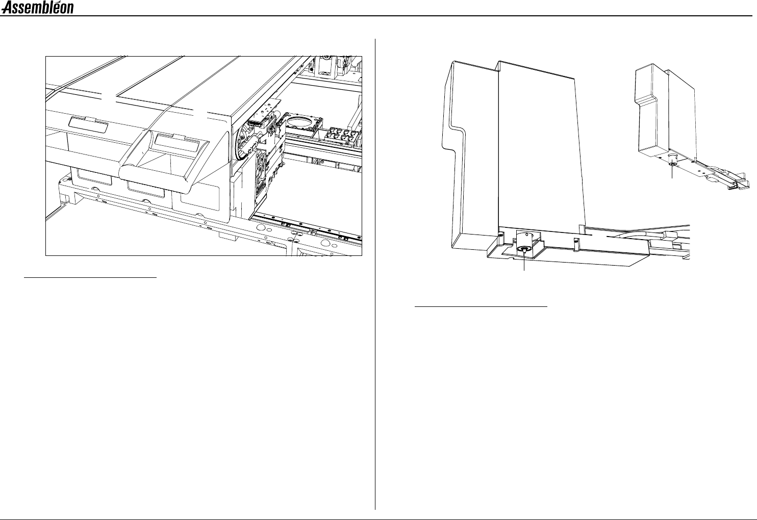
2.4.2 Placement head
Figure 13 Placement head laser vision (left), Placement head single vision (right)
1 BA (board alignment) camera.
2 Component laser. The component laser is optional:
• Present on placement head laser vision
• Absent on placement head single vision
3 RZ unit for component handling.
4 Toolbit, kept in place by magnetic force,
toolbit overview see 2.4.5. Toolbits.
2
1
3
4
5
3
1
2
4
3
1
4
4022 593 51894 Operating Manual
09.01 AX-301/501, AX-3/5 16
2
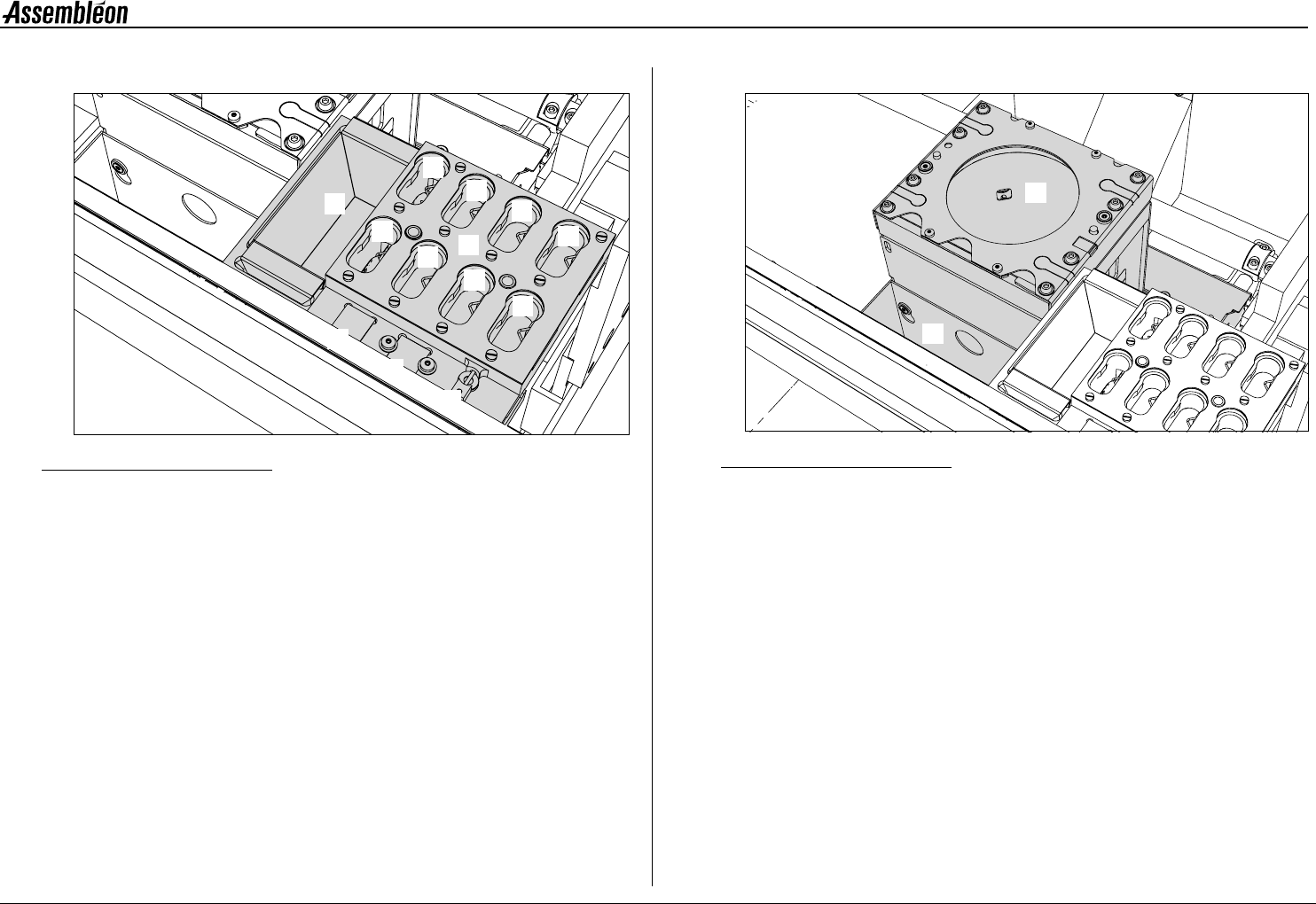
2.4.3 Toolbit exchange unit
Figure 14 Toolbit exchange unit
A Toolbit slots, for unused toolbits.
B Component dump bin (standard).
C Vacuum calibration pad.
D Light calibration pad for the BA camera.
E Melf vacuum calibration tool.
2.4.4 CV camera
Figure 15 CV camera
1 CV (component vision) camera.
2 Large component dump bin.
1
2
3
4
5
6
7
8
B
C
D
E
A
1
2