AX501最新3.6x版英文操作手册.pdf.pdf - 第34页
4022 593 51894 Operatin g Man ual 09.01 AX-301/501, AX-3/5 34 8 8.4 Remo v e the support plates Figure 40 Remove the board support plates NOTE: Use, when necessary, the stepstool to prevent an unsafe work load. 1 Mov e r…
4022 593 51894 Operating Manual
09.01 AX-301/501, AX-3/5 33
8
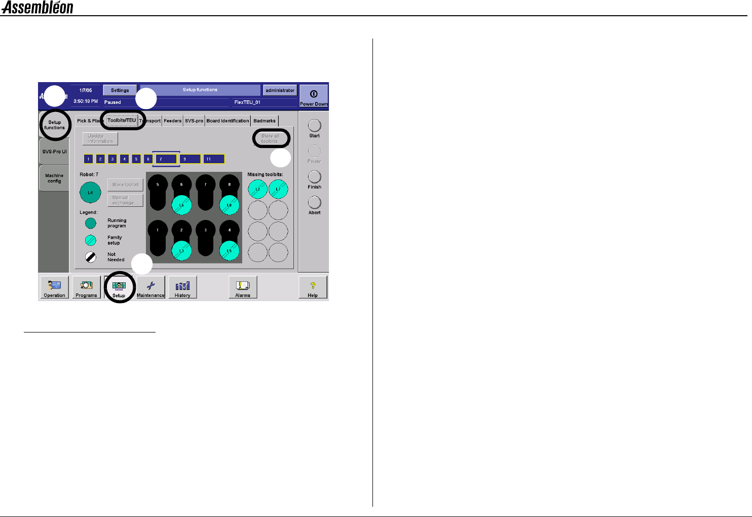
8.3 Move all toolbits to the toolbit exchange
units
Figure 39 Move all toolbits to the toolbit exchange units
To move all toolbits from the placement heads to the toolbit exchange
unit:
• Select ’Setup’ (1).
• Select ’Setup functions’ (2).
• Select ’Toolbit/TEU’ (3).
• Select ’Store all toolbit’ (4).
1
2
3
4
4022 593 51894 Operating Manual
09.01 AX-301/501, AX-3/5 34
8
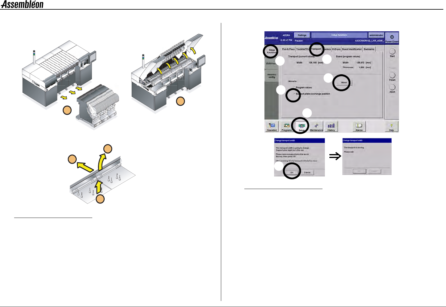
8.4 Remove the support plates
Figure 40 Remove the board support plates
NOTE: Use, when necessary, the stepstool to prevent an unsafe
work load.
1 Move rear transport rail to its most rear position.
Figure 41 Moving the rear transport rail to its most rear position
•
Select ’setup’ (a), ’setup functions’ (b), ’transport tab’ (c),
’support plates exchanges position’ (d), followed by ’move’(e).
• Check if the transport is free to move and confirm (f).
• Wait until the transport rail has finished its movement.
2 Remove all trolleys.
3 Open all robots, run-in and run-out covers.
4 Take away the rear support strips.
5 Take out the support plates.
6 Clean the transport area, trolley slots and dump bins with a
vacuum cleaner.
2
1
5
4
3
f
a
e
d
b
c
4022 593 51894 Operating Manual
09.01 AX-301/501, AX-3/5 35
8
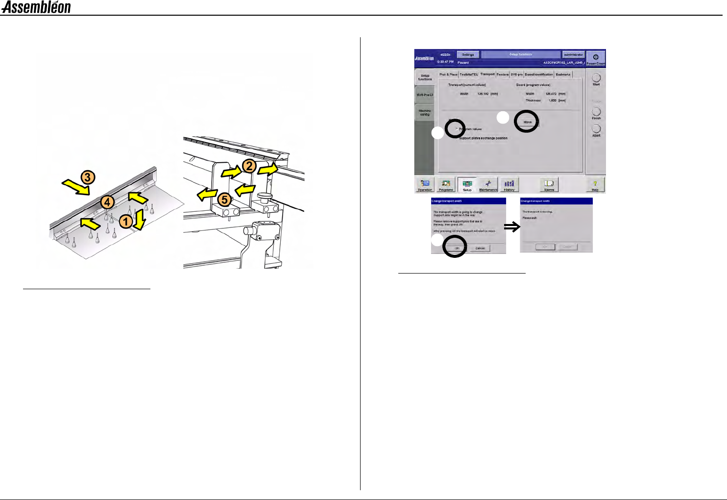
8.5 Install the support plates
Figure 42 Install the board support plates
NOTE: Use, when necessary, the stepstool to prevent an unsafe
work load.
1 Mount the prepared support plates on the transport beam in the
right order.
NOTE: Avoid shifting of the pins on the support plates
2 Loosen the stoppers and slide them against the front transport rail.
3 Move the rear transport rail to the ’board width’ position.
Figure 43 Board width settings
•
Select ’program values’ (a), and select ’move’ (b).
• Check if the transport is free to move and confirm (c).
• Wait until the rear transport rail has finished its movement.
4 Always re-place the board support strips and push them against
the rear transport rail.
5 Push a ’new’ board into the run-in to check the transport width
and position the stoppers equally along the board.
6 Check the position of the low speed sensor.
c
b
a