AX501最新3.6x版英文操作手册.pdf.pdf - 第17页
4022 593 51894 Operatin g Man ual 09.01 AX-301/501, AX-3/5 17 2 2.4.5 T oolbits Figure 16 T oolbits survey Each compon ent is handl ed with its prescribed t oolbit. Figure 17 T oolbits, survey T oolbit type Package types…
4022 593 51894 Operating Manual
09.01 AX-301/501, AX-3/5 16
2
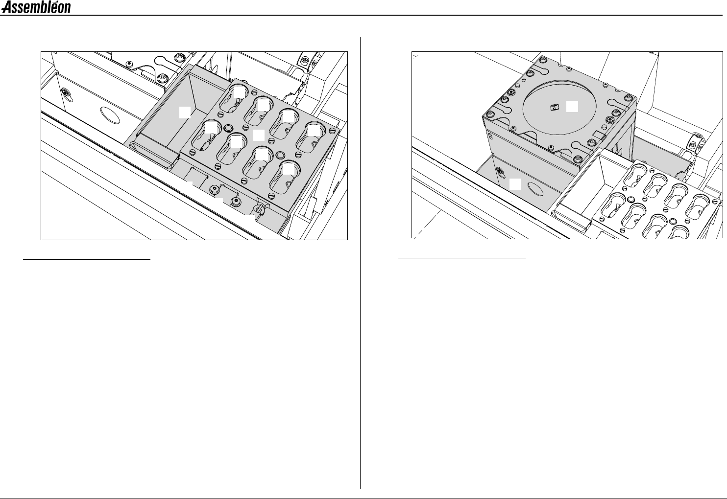
2.4.3 Toolbit exchange unit
Figure 14 Toolbit exchange unit
A Toolbit slots, for unused toolbits.
B Component dump bin (standard).
C Vacuum calibration pad.
D Light calibration pad for the BA camera.
E Melf vacuum calibration tool.
2.4.4 CV camera
Figure 15 CV camera
1 CV (component vision) camera.
2 Large component dump bin.
1
2
3
4
5
6
7
8
B
C
D
E
A
1
2
4022 593 51894 Operating Manual
09.01 AX-301/501, AX-3/5 17
2
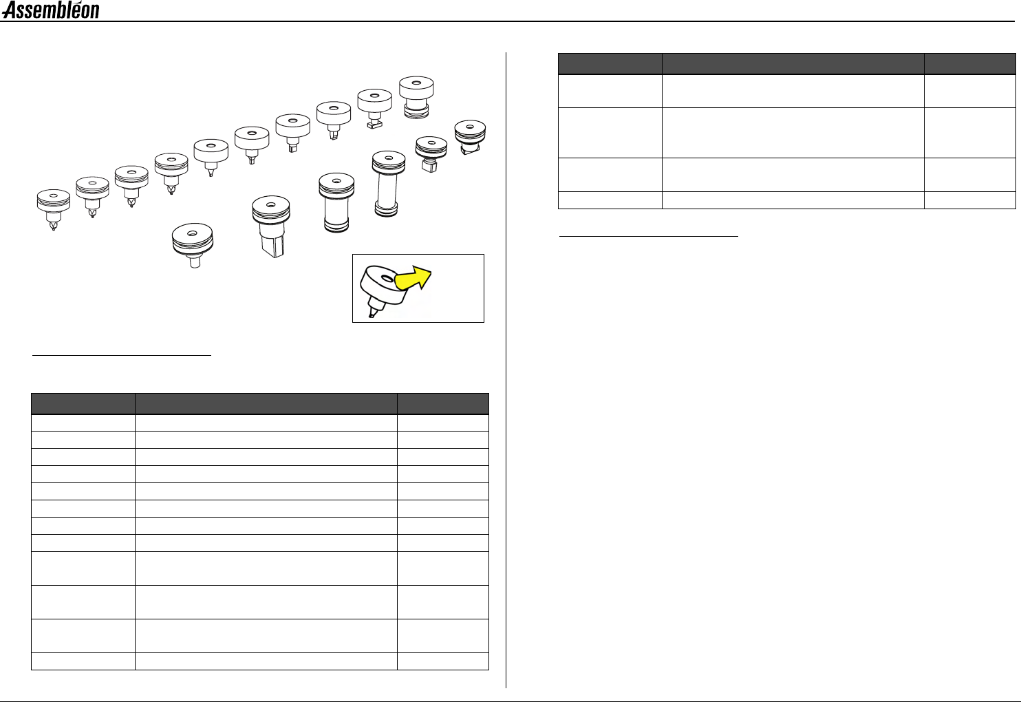
2.4.5 Toolbits
Figure 16 Toolbits survey
Each component is handled with its prescribed toolbit.
Figure 17 Toolbits, survey
Toolbit type Package types Align type
CPL1 R/C01005 Laser
CPL2 R/C0201..R/C0402 Laser
CPL3 R/C0402..R/C0603 Laser
CPL4 R/C0603..R/C1206 Laser
L3 R/C0402..R/C0603 Laser
L4 R/C0603..R/C1206 Laser
L5 R/C1206..R/C2516 SO14..SO16 Laser
L6 MELF Laser
L7 BGA, SO, SOJ, SSOP, TSSOP,
VSO, QFP, TANT and PLCC
Laser
L8 BGA, SO, SOJ, SSOP, TSSOP, VSO,
QFP and PLCC
Laser/
Camera
V3 BGA, Flip-Chip etc. Laser/
Camera
V4 Low connectors Camera
L5
L7
L8
CPL3
L3
L6
L4
V4
V5
V6
V7
V3
CPL4
V8
CPL2
CPL1
Toolbit
name
V5 BGA, SO, SOJ, SSOP, TSSOP, VSO,
QFP and PLCC
Camera
V6 BGA, SO, SOJ, SSOP, TSSOP, VSO,
QFP and PLCC, handling below 'component
laser’
Camera
V7 All BGA, SO, SOJ, SSOP, TSSOP, VSO,
QFP, TANT and PLCC
Laser/
Camera
V8 High connectors Camera
Toolbit type Package types Align type
4022 593 51894 Operating Manual
09.01 AX-301/501, AX-3/5 18
2
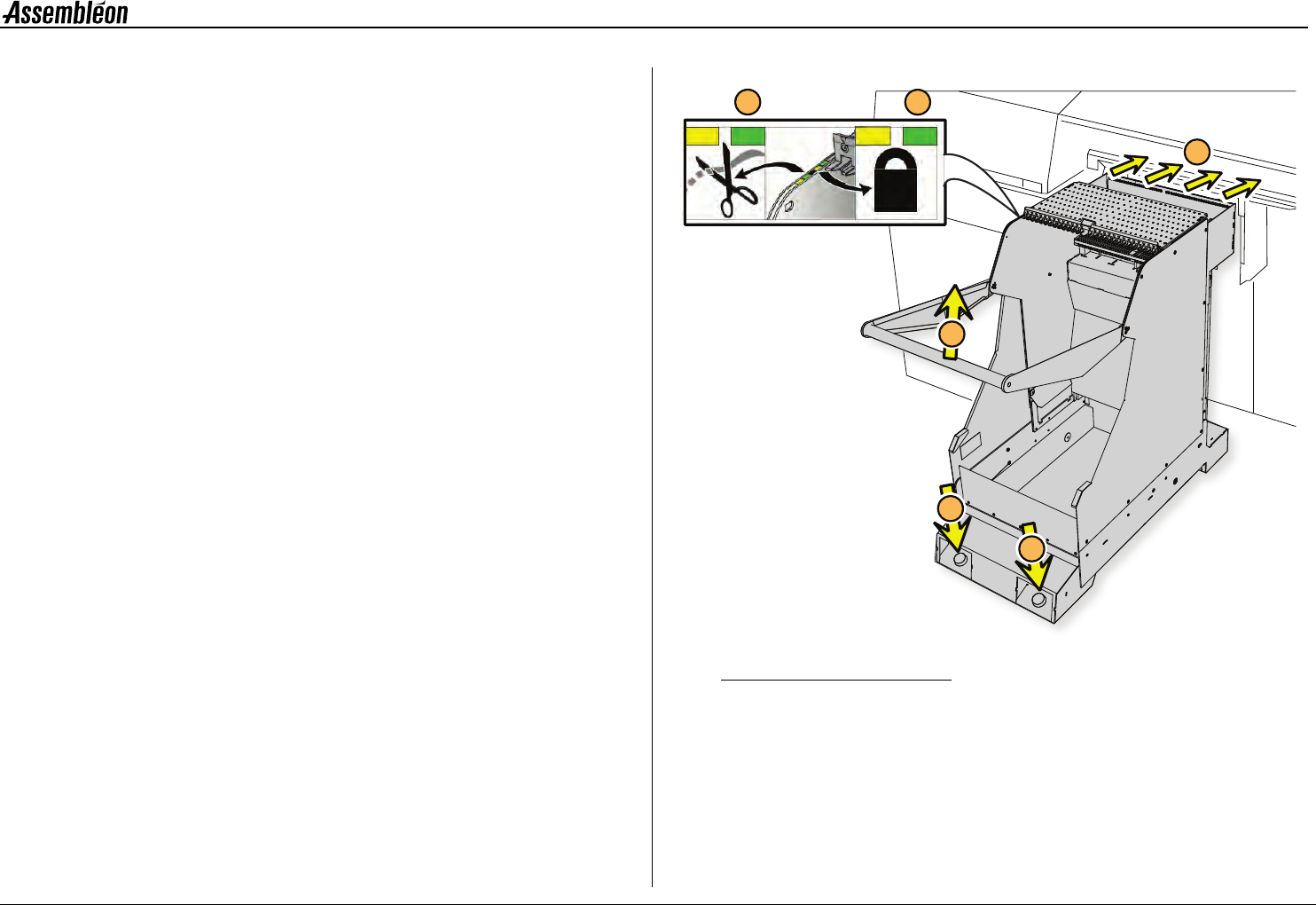
2.5 Feeder trolley handling
2.5.1 Placing and removing an A-series feeder trolley
NOTE: A feeder trolley can only be placed and removed with the
main switch of the machine turned on. Remove the trolley
lift cover before placing a feeder trolley, see 2.5.3.
Clean the feeder trolley position with a vacuum cleaner.
• Take the handle (1) and roll the feeder trolley to the machine.
• Position the feeder trolley in the required trolley slot (2). If
positioned correctly the yellow LED (3) is on.
• Push the button (4) until the feeder trolley is fully lifted. When
locked, the green LED (3) is on.
• If a tape cutter is mounted on the trolley, the tape cutter will
cut once after the trolley is fully lifted. When ready to function,
the green LED (5) is on
■ Remove the feeder trolley by pushing the button (6).
Figure 18 Placing the A-series feeder trolley
4
2
6
1
5
3