YS24X_Mainte_E.pdf - 第100页
3-33 3 Periodic maintenance items 4.2 Checking the ejector vacuum pressure Check the v acuum level of each ejector of the ejector unit to see if it is working correctly . When the level does not reac h the specified vacu…
3-32
3
Periodic maintenance items
4. Three-month inspection
4.1 Cleaning and replacing the ejector filter
Although depending on the air supply conditions and operating time, ejectors should be inspected once every
3 months. Use an air blow tool to remove dust buildups when small. We recommend replacing the air filter if
heavy dust deposits are found.
e
1
Make the preparations for the
cleaning and replacing work.
1. Press the emergency stop button and
then open the machine safety cover.
2. If the machine is equipped with a
carriage, remove the carriage to allow
you to easily access the head.
3. Move the head unit forward.
4. Place a square cloth under the head unit.
2
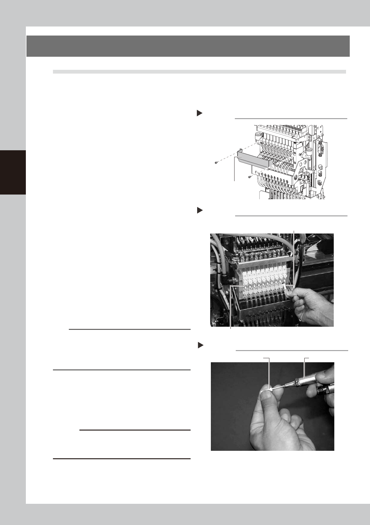
Remove the baffle plate.
Remove the baffle plate using the hex
wrench.
53396-L4-00
3
Remove the filter cap.
Loosen and remove the filter cap with a
slotted screwdriver.
53331-L4-00
4
Clean the filter.
Use tweezers to take the filter out of the
ejector. When there is only a little dust in the
filter, use an air blow tool to blow it away
and return the filter back to the original
position.
53332-L4-00
n
NOTE
If there are heavy dust deposits in the filter or the filter
has discolored, replace it with a new filter (K46-M8527-
C0X). As a general guide, filters should be replaced
once every 3 months, although this depends on the
actual operating time.
5
Reattach the filter cap.
1. Fit the filter into the filter cap and insert it
into the ejector.
2. Turn the filter cap to the right until it locks
and clicks.
c
CAUTION
When attaching the filter, be careful to make sure the
O-ring does not come out from between the manifold
and the filter cap.
6
Reattach the baffle plate.
1. Reattach the baffle plate at its original
position using the hex wrench.
2. Remove the square cloth.
Removing the filter cap
Step 3
Ejector unit
Ejector filter
Filter cap, O-ring
Cleaning the filter
Step 4
Air blow toolFilter
Step2
Removing the baffle plate
Baffle plate
3-33
3
Periodic maintenance items
4.2 Checking the ejector vacuum pressure
Check the vacuum level of each ejector of the ejector unit to see if it is working correctly.
When the level does not reach the specified vacuum level, the valve or the ejector BIT may need to be
replaced. See chapter 6, "3.Ejector unit" to replace the valve or the ejector BIT.
e
1
Move the head unit forward.
1. Press the emergency stop button and
then open the machine safety cover.
2. If the machine is equipped with a
carriage, remove the carriage to allow
you to easily access the head.
3. Move the head unit forward.
2
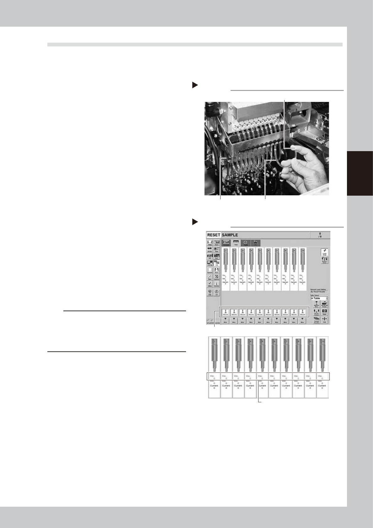
Remove the air hoses from the air
joints at the bottom of the head.
Remove all air hoses from the air joints at the
bottom of the head. Do not remove them at
the top.
53333-L4-00
3
Check the ejector vacuum level.
1. Open the [Unit] - [Head] screen.
2. Press the [Vacuum] button while blocking
the tip of air hose with your finger..
3. Make a note of the "Max" reading of
each head while the air hose is blocked,
and check that the reading is higher
than the criterion value below.
Make the same check for all heads.
54305-L4-10
n
Criterion of ejector vacuum level
When air joint is blocked: 190 or more
TIP
If the vacuum level of any head does not reach the
criterion value, then check the air path in the head
(interior of the spline shaft or air hose between the
ejector and spline shaft). Clean or replace it if
necessary
4
Return the air hoses to the original
position.
Disconnecting the air hoses
Step 2, 3
Air hose disconnected (transparent hose)
Block the air hose with your finger during measurement.
Bearing holder
Checking the vacuum levels
Step 3
Press the [Vacuum] button for each head.
Check "Max" vacuum levels
(with air joint blocked).
3-34
3
Periodic maintenance items
4.3 Operation check of head blow valve and cleaning blow valve
Check the operation of the head unit valve (solenoid valve). The head unit valve includes the following. One is
the blow valve that blows per head unit. The other one is the cleaning blow valve that blows strongly to clean
the inside of the shaft. If the valve does not work properly, it needs to be replaced. Replace it referring to
chapter 6, "3.2 Replacing a valve (solenoid valve)" and "3.3 Replacing the cleaning blow valve".
c
CAUTION
A strong air flow is exhausted during the cleaning blow. Always remove all nozzles attached to the heads before
starting the cleaning blow. Starting the cleaning blow while the nozzles are still attached may blow the nozzles away
from the heads causing the nozzles to break or become lost.
1
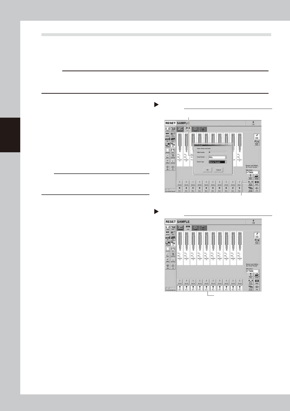
Remove the nozzles from all heads.
If nozzle station is equipped with the machine:
1. Press the [Nozzle Change] button on the
[Unit] - [Head] screen.
2. Select "ALL" for the Head Number and
select "Store Nozzle" for Nozzle type on
the "Nozzle Change" screen.
3. Press the [OK] button. The nozzles of all
heads are stored to the nozzle station.
54313-L4-00
n
NOTE
If the machine is not equipped with the nozzle station,
press the emergency stop button and then open the
machine safety cover to remove nozzles manually.
e
2
Move the head unit forward.
1. Press the emergency stop button and
then open the machine safety cover.
2. If the machine is equipped with a
carriage, remove the carriage to allow
you to easily access the head.
3. Move the head unit forward.
3
Blow each head.
Press all the [Blow] buttons on the [Unit] -
[Head] screen.
54306-L4-10
4
Check the blowing condition.
Place finger under each head. Check that
the air is exhausted equally from all heads. If
the less air is exhausted or the air is not
exhausted, a valve (solenoid valve) needs
to be replaced. Replace it referring to
chapter 6, "3.2 Replacing a valve (solenoid
valve)".
Storing nozzles
Step 1
Head Number : “ALL ”, Nozzle Type : “Store Nozzle”
[Nozzle Change] button
Blowing
[Blow] button
Step 2