YS24X_Mainte_E.pdf - 第30页
xxvii Safety instructions Potential hazard Could cause machine damage (collisions with head, etc.). T o avoid hazard V erify that no objects have been placed on the top cover of the feeder exchange carriage (for YSM40 an…
xxvi
Safety instructions
Potential
hazard
Could cause machine damage (collisions with head, etc.).
To avoid
hazard
Verify that no objects have been placed on the top cover of the feeder exchange carriage (for
YSM40).
Applicable
machines
Feeder exchange carriage (YSM40)
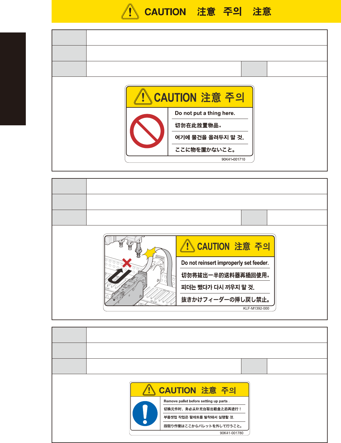
Case
Setup
Potential
hazard
The carrier tape could make contact with the head, possibly causing machine damage.
To avoid
hazard
When a feeder is extracted from its loaded position, be sure that the feeder has been completely
extracted before pressing it back into its loaded position.
Applicable
machines
Z:LEX(YSM20/YSM20W), YSM40/YSM40R
Case
Setup
Potential
hazard
Pallet may drop if setting up components on the component supply station.
To avoid
hazard
Remove pallets before setting up components.
Applicable
machines
cATS (YSM40/YSM40R)
Case
Setup
xxvii
Safety instructions
Potential
hazard
Could cause machine damage (collisions with head, etc.).
To avoid
hazard
Verify that no objects have been placed on the top cover of the feeder exchange carriage (for
YSM40 and Z:LEX (YSM20
))
.
Applicable
machines
Feeder exchange carriage
(YSM40/YSM40R, Z:LEX(YSM20/YSM20W))
Case
Setup
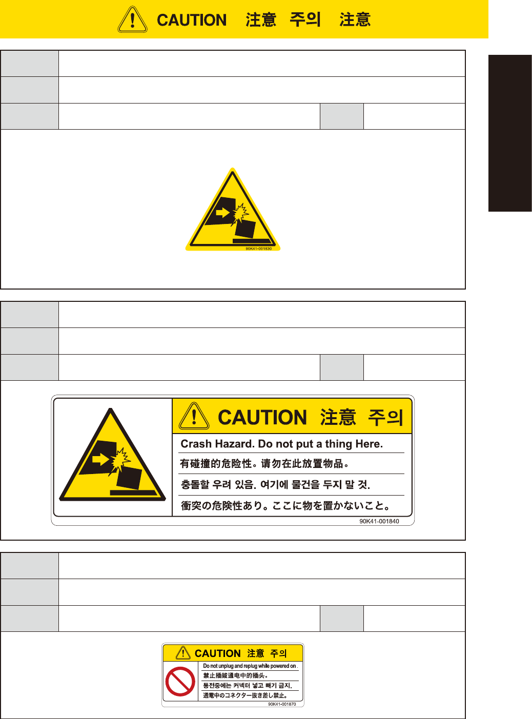
Potential
hazard
Could cause machine damage (collisions with head, etc.).
To avoid
hazard
Verify that no objects have been placed on the top cover of the feeder exchange carriage (for YSM40
and Z:LEX (YSM20)).
Applicable
machines
Feeder exchange carriage
(YSM40/YSM40R, Z:LEX(YSM20/YSM20W))
Case
Setup
Potential
hazard
Machine damage
To avoid
hazard
Do not insert or remove any connector while power is on.
Applicable
machines
cATS10 (Z:LEX(YSM20/YSM20W) )
Case
Setup
xxviii
Safety instructions
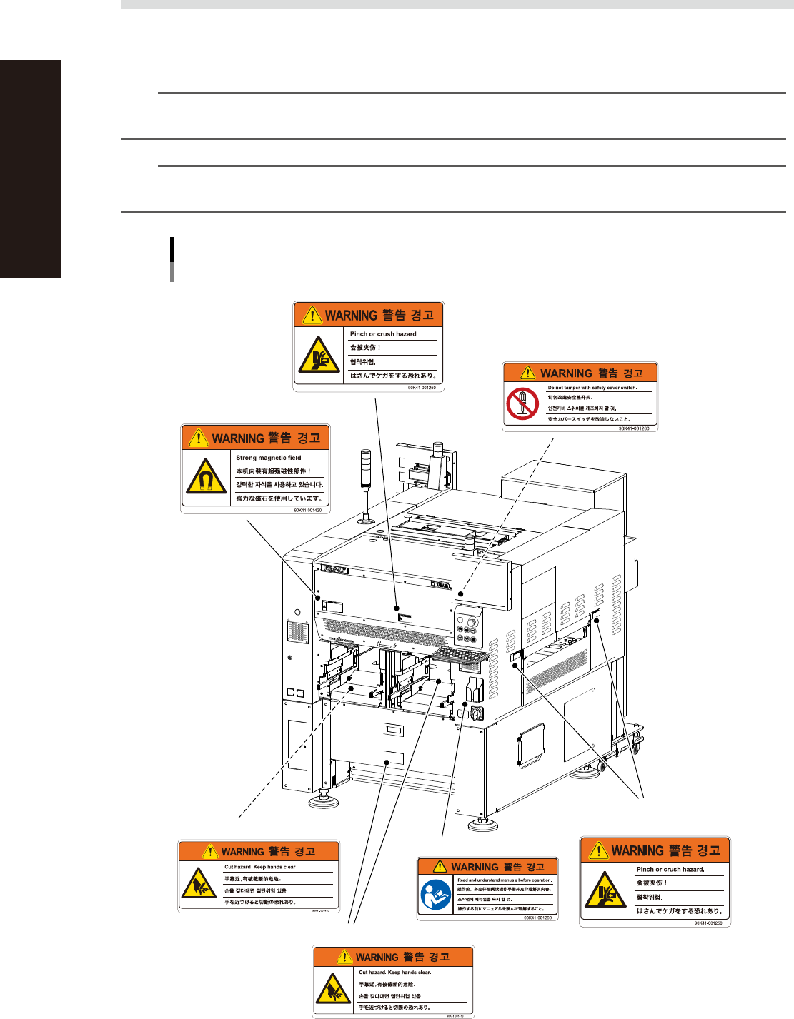
3.4 Label positions
The following warning/caution labels are attached to the YAMAHA products to ensure safe and correct use.
Check that the information on each label is clearly legible and comply with the instructions.
For safety precautions other than those on the labels shown in this section, see the instructions in "1. Safety".
n
NOTE
Basically, labels are attached to the positions shown below, although they may differ slightly depending on the
machine model.
n
NOTE
When connecting power to this equipment, refer to "Power connection terminals" described in the appendix of the
maintenance manual or user's manual.
Warning/caution labels
Front 1
■ Open/close cover (front and rear sides)
■ Open/close cover inner side
(front and rear sides)
■ Open/close cover
(front and rear sides)
■ Main switch
■ Cutter inner side
■ Cutter section
■ Conveyor opening
(front and rear sides, right and
left sides)
93201-L4-10