YS24X_Mainte_E.pdf - 第8页
v Safety instructions 1.8 Keeping hands away from moving par ts During use of this machine, the customer’ s equipment and operating conditions might allow the oper ator’ s hands to come into contact with moving parts. Us…

iv
Safety instructions
1.4 Cautions during machine operation
• Always make pre-operation checks before turning on the main power switch.
• Do not use an air blow tool when cleaning the machine. (Airborne dust will badly affect machine operation.)
• Stop all machine operation before cleaning around the machine.
• Do not turn off the air during operation.
• Always make periodic inspections to prevent unexpected machine breakdowns.
• Allow only properly trained, experienced workers to perform repair and adjustment.
1.5 Cautions during power outage
If a power outage (blackout) occurs during automatic machine operation, always turn the main power switch
off to prevent faulty operation and equipment damage after power has been restored. Remove items such as
boards that remain inside the machine.
1.6 Cautions regarding ferromagnetic fields
Some machines contain parts generating strong magnetic fields which may cause death, bodily injury, or
device malfunction. Always comply with the following instructions.
• Persons wearing electronic medical devices such as cardiac pacemakers and/or hearing aids must not put
any of their body parts into the machine.
• Persons wearing ID cards, purses, and/or wristwatches must keep away from the linear motor.
• Do not attempt to disassemble the linear motor (including surrounding covers).
• Do not bring tools close to the linear motor.
• Do not bring tools close to the magnetic scale.
• Do not put magnetic materials or objects close to the linear motor.
• Do not touch a portion close to the linear motor during operation or immediately after the operation has been
finished since such part is hot.
c
CAUTION
When disposing of a part generating strong magnetic fields such as a linear motor, dispose of it in compliance with
the laws and regulations of the country where the machine is used. If you have any questions about disposal of the
parts, please contact our sales representatives.
1.7 Handling the internal tape cutter
• Never supply electrical power and air to the machine while the covers for the tape cutter are removed.
• Tape cutter maintenance tasks must be performed by YAMAHA service personnel.
v
Safety instructions
1.8 Keeping hands away from moving parts
During use of this machine, the customer’s equipment and operating conditions might allow the operator’s
hands to come into contact with moving parts.
Use the following safety measure options to avoid possible danger where openings or gaps are found on the
machine.
n
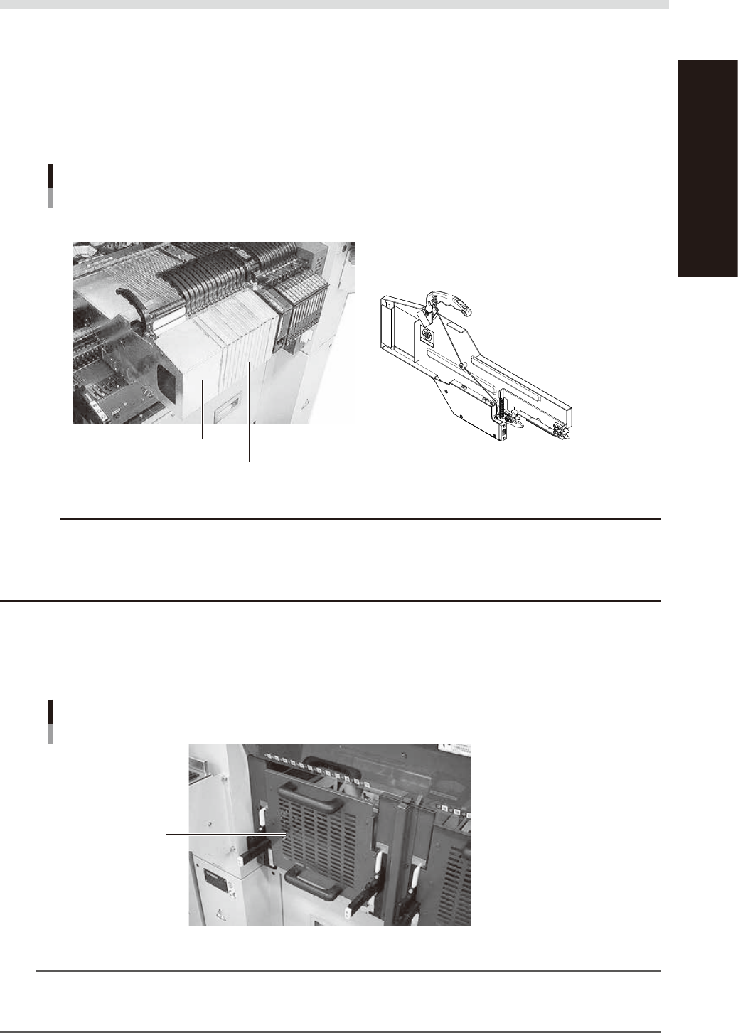
Dummy feeder
Use dummy feeders as safety measures to fill a gap between tape feeders. Install dummy feeders on the feeder plate the
same way as normal feeders in order to prevent hands from entering.
Prevention of hand entry
Dummy feeder
Dummy feeder (8mm-size)
Dummy feeder (Wide-size)
Clamp lever
91203-L0-20
c
CAUTION
To install or remove a dummy feeder, be sure to first press the emergency stop button and then open the cover. The
machine has a structure that does not allow installing or removing a dummy feeder when the machine is in operation.
However, inserting a dummy feeder inside the cover during operation may cause serious accidents, so be careful not
to attempt it.
n
One-stop cover (for machines designed for use with feeder exchange carriage, excluding YSM40/YSM40R)
If not using a feeder exchange carriage in the machine that is to be used with feeder exchange carriages, install a
one-stop cover in the position where a feeder exchange carriage is to be installed.
Prevention of hand entry
One-stop cover
One-stop cover
91204-L0-10
n
NOTE
One-stop covers cannot be installed or removed during operation. The machine must be in a stopped state because
the section where a feeder exchange carriage is to be installed will move up and down for the installation or removal
of the feeder exchange carriage.
vi
Safety instructions
n
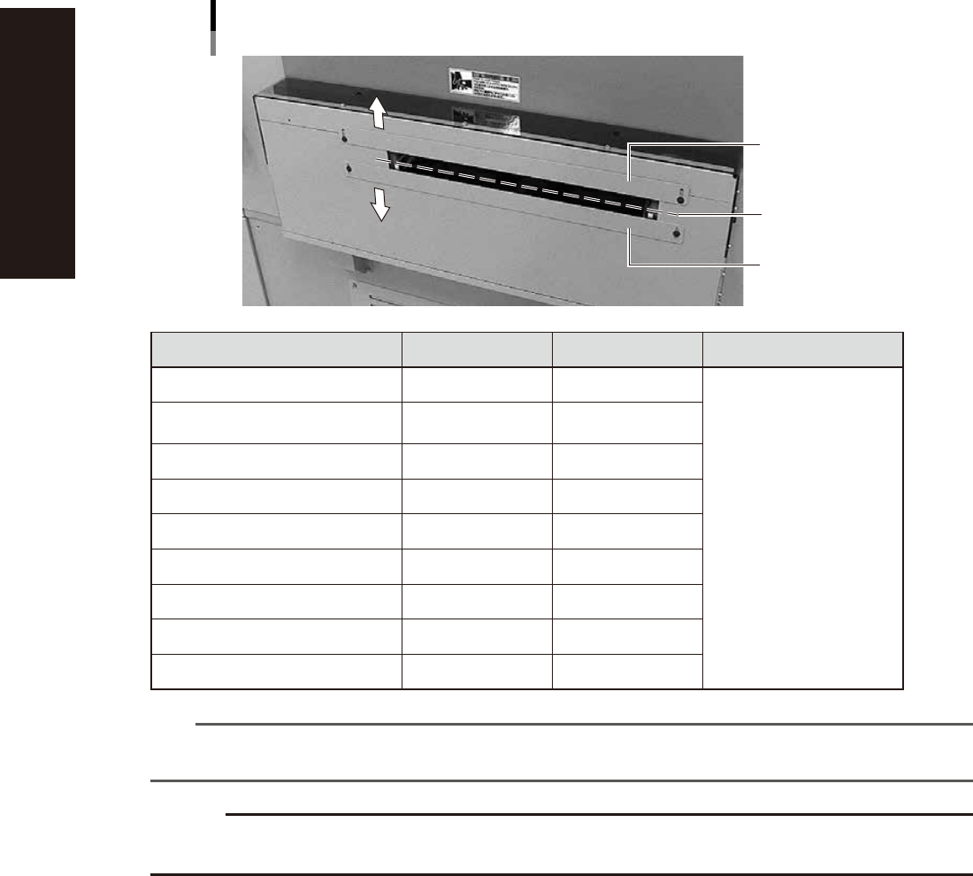
Muzzle plate
Use these plates as a safety measure for the board conveyor entrance and exit openings. Each plate is movable, so adjust
the mounting position to match the boards to be produced.
Muzzle plate
Upper muzzle plate
Lower muzzle plate
Board conveyance plane
91205-L0-00
Upper clearance Lower clearance Remarks
YS100, YS88 8.0 to 38.5mm 1.0 to 31.0mm
From board conveyor plane
YS12, YS12P, YS12F, YS24,
YS24X,YSD
5.0 to 20.0mm 4.2 to 39.2mm
YSM40/YSM40R 0 to 44.0mm 0 to 39.0mm
Z:LEX(YSM20/YSM20W) 0 to 36.0mm 4 to 40.0mm
YSM10 0 to 44.0mm 4 to 40.0mm
YC8 13.4 to 80.4mm 4.6 to 39.2mm
YSB55w 0 to 10mm 6mm (fixed)
YSP 0 to 6.6mm 0 to 26.4mm
YSi-V 0 to 48.0mm 0 to 102mm
n
NOTE
The values above show the maximum adjustable range of the muzzle plate.
See the product specification of each machine for the component mountable height and the restrictions of the substrate.
c
CAUTION
When installing a unit such as a loader or an unloader on the upstream or the downstream side of the machine, set the
muzzle plates to the opening of the board conveyor entrance or the board conveyor exit to make the opening small.