YS24X_Mainte_E.pdf - 第82页
3-15 3 Periodic maintenance items 3. T wo-month inspection 3.1 Cleaning and greasing the X and Y axes T his section describes how to clean and grease the X and Y axes. See "Chapter 5 Lubrication points and schedule&…
3-14
3
Periodic maintenance items
2.2 Inspecting each axis
Inspect the ball screws on the X, W, U, and PU (Push-up) axes and the guides on the X, Y, W, and U axes. The
checkpoints are listed below.
A grease spattering prevention cover is attached to the X-axis ball screw. Before starting the inspection work,
detach this grease spattering prevention.
TIP
See "3.1 Cleaning and greasing the X and Y axes" described later on for detaching or attaching the anti grease
splatter cover.
TIP
See "3.1 Cleaning and greasing the X and Y axes", "3.2 Cleaning and greasing the push-up axis (PU-axis)", "4.7 Dual
stage only: Cleaning and lubrication of U axis (W2 axis)" and "5.2 Cleaning and lubricating the W-axis" in this chapter,
and "Chapter 5 Lubrication points and schedule" for positions of ball screws and guides of each axis.
Checkpoints
1. Any foreign matter adhering to the ball screws and guides?
Check if any fallen chips have adhered to the X and Y axis ball screws and/or X, Y and W axis guides.
2. Do the ball screws and guides have the correct amount of grease?
Check if grease has flowed off or splattered in the air failing to adhere. Also check if grease has discolored or hardened.
e
3. Any abnormal sounds from the ball screws?
Press the emergency stop button. Then check for any abnormal sounds while pressing the X-axis by hand.
Countermeasures
1. Ball screws and guides may be damaged when chips and other material bite into them. If chips are adhering, wipe
them off along with the grease or remove with tweezers, etc.
2. Apply grease referring to "3.1 Cleaning and greasing the X and Y axes", "3.2 Cleaning and greasing the push-up axis
(PU-axis)", "4.7 Dual stage only: Cleaning and lubrication of U axis (W2 axis)" and "5.2 Cleaning and lubricating the
W-axis" in this chapter described later on.
3. Contact YAMAHA sales representative when abnormal sounds occur even after trying the countermeasures in the above
steps 1 and 2.
w
WARNING
THIS MACHINE CONTAINS PARTS GENERATING STRONG MAGNETIC FIELDS. GREAT CARE SHOULD BE TAKEN WHEN A PART
OF YOUR BODY IS PUT INSIDE THE MACHINE FOR THE MAINTENANCE WORK. CAUTIONS REGARDING FERROMAGNETIC
FIELDS ARE DESCRIBED IN THE SECTION, "SAFETY INSTRUCTIONS", AT THE BEGINNING OF THIS DOCUMENT. ALWAYS
THOROUGHLY READ THIS SECTION TO FULLY UNDERSTAND ITS CONTENTS.
3-15
3
Periodic maintenance items
3. Two-month inspection
3.1 Cleaning and greasing the X and Y axes
This section describes how to clean and grease the X and Y axes. See "Chapter 5 Lubrication points and
schedule" for lubrication points and lubrication form. Prepare a grease gun and specified grease (NSL).
c
CAUTION
When performing the cleaning and greasing work, use square bandages to prevent parts from being lost or entering
the Y-axis linear part.
c
CAUTION
For information on the use of grease, read the caution items for handling in "Safety instructions" and chapter 1, "2.2.2
Lubricating tools and grease".
c
CAUTION
If abnormal sound is heard from the X and Y axis ball screws or guides, contact YAMAHA sales representative.
Disassembly and cleaning of the ball screws or guides by the user will void the warranty.
3.1.1 Cleaning and greasing the X-axis ball screw
For YS24X with sATS II, it is recommended to perform the service work from the front of the machine for both
the table A(at the front side) and the table B(at the rear side). The work procedure for each table is separately
shown below.
n
A-table
The procedure for the service from front side of the machine is described in the following.
1
Make the preparations for the
cleaning and greasing work.
e
1. Take off all accessories susceptible to the
magnetic fields, such as a wristwatch
and/or magnetic ID card.
2. Press the emergency stop button and
then open the machine safety cover.
3. If the machine is equipped with a
carriage, remove the carriage.
4. Place a square cloth on the Y-axis linear
area and the push-up plate.
2
Remove the grease spattering
prevention cover.
1. Move the A-table's head unit all the way
to the front of the machine.
2. Move the head unit to the right side and
loosen two mount screws on the left of
the grease spattering prevention cover
with Philips Screwdriver.
53311-L4-00
3. Move the head unit all the way to left,
remove two mount screws on the right of
the grease spattering prevention cover
with Philips Screwdriver.
Removing the screws holding the cover
Phillips screwdriver Grease spattering prevention cover
Step 2-2
3-16
3
Periodic maintenance items
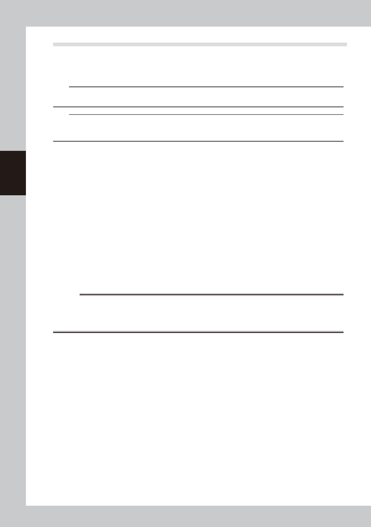
4. Remove the grease spattering prevention
cover by pulling it to the right.
53312-L4-00
TIP
When it is difficult to access the anti grease splatter
cover, prepare a step.
TIP
When attaching the anti grease splatter cover, follow
the reverse order of procedure described above.
3
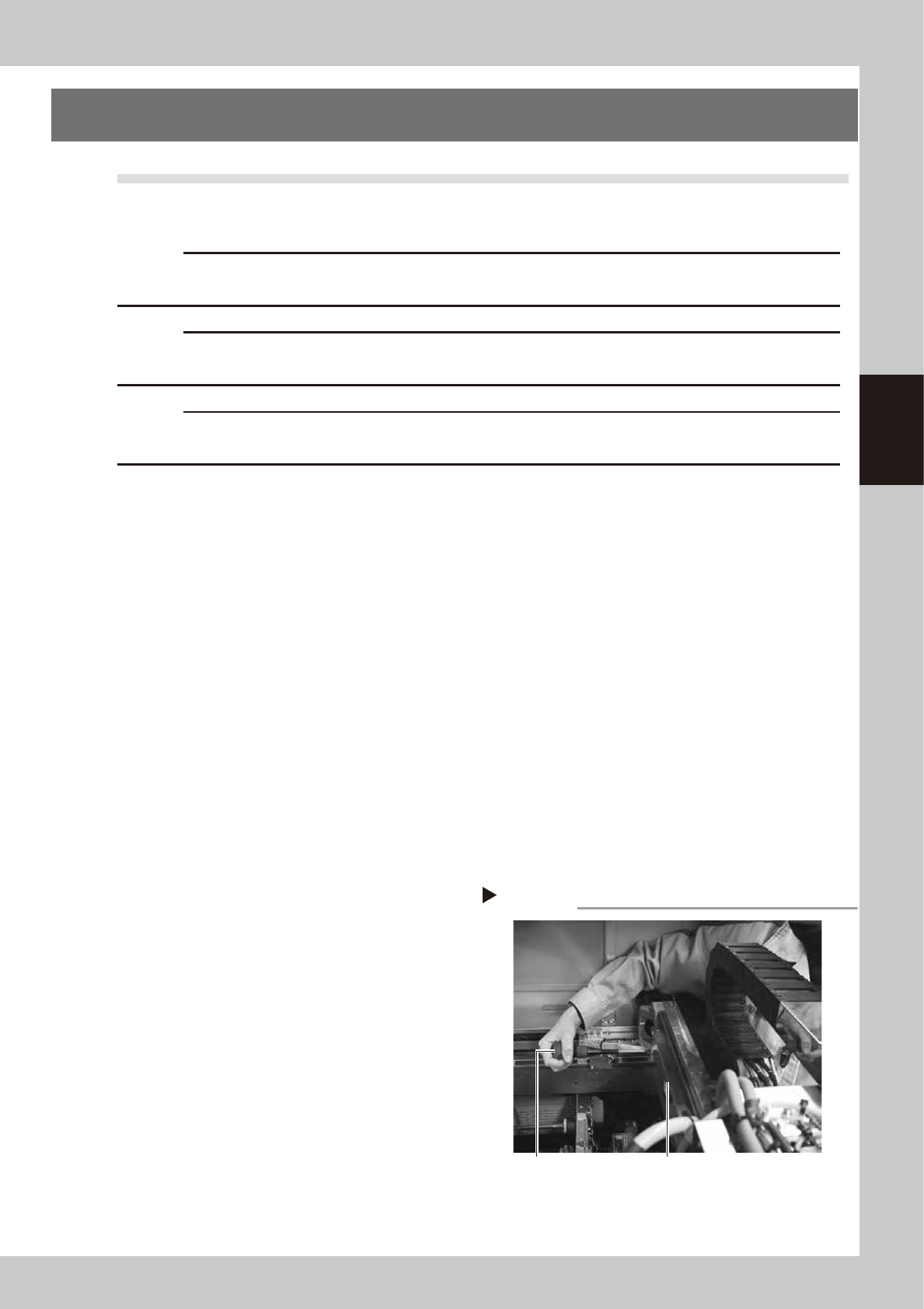
Clean the ball screws.
1. Using the handle, move the head unit to
one end of each axis.
2. Wipe away the old grease and dirt from
the ball screw with a lint-free cloth that
does not raise dust (for clean room use).
3. Move the head unit to the opposite side,
and wipe the ball screw also on the
opposite side.
53313-L4-00
n
NOTE
Wipe away the old grease and dirt in the lead groove
of the ball screw. Also check that no debris or residue
remains in the lead groove.
4
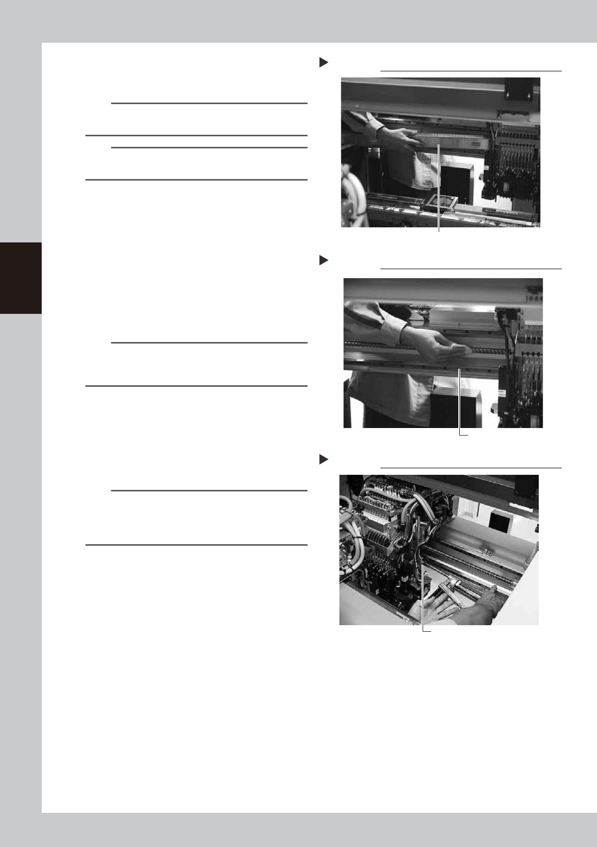
Apply grease to the ball screws.
Set the standard nozzle on the grease gun,
and inject the specified grease (NSL) from
the grease nipple (at the opposite side of
the X axis motor).
53314-L4-00
n
NOTE
LRepeat the process below, and inject until the new
grease flows over the gap.
• Injection of grease
• Move the axis with hand a little
Greasing the X-axis ball screw
Step 4
Grease nipple for
X-axis ball screw
Cleaning the X-axis ball screw
Step 3
Cleaning cloth
Removing the X-axis grease spattering prevention cover
Grease spattering prevention cover
Step 2-4