IPC 7711A.pdf - 第172页
NOTES IPC-771 1A Number: 5.5.6 Revision: Date: 2/98 Subject: Gull Wing Installation P a g e2o f2 Copyright Association Connecting Electronics Industries Provided by IHS under license with IPC Not for Resale No reproducti…
EQUIPMENT REQUIRED
Soldering system(s)
1 or 2 Soldering handpieces
Blade tip
MATERIALS
Flux-cored solder
Flux
PROCEDURE
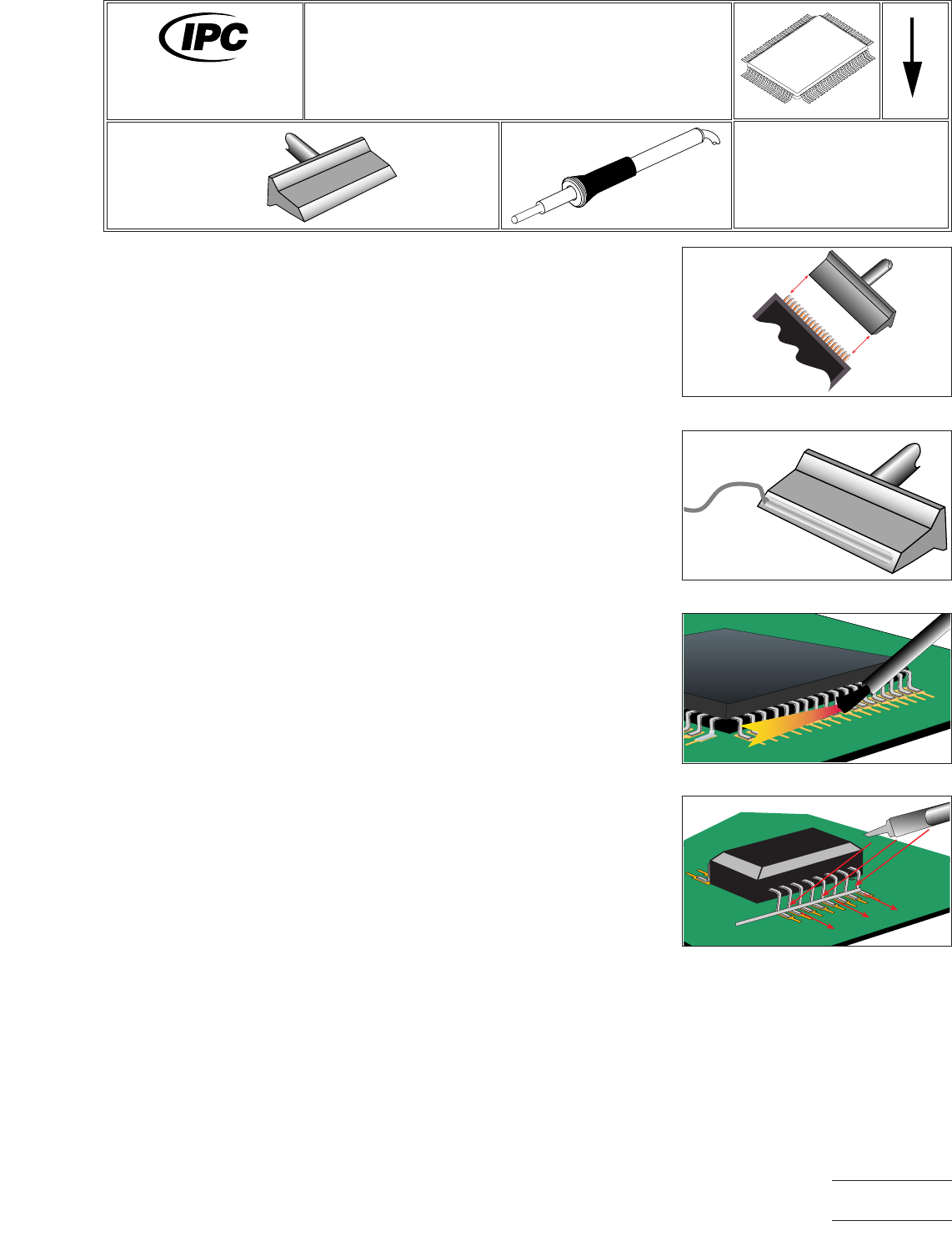
1. Select a blade tip appropriate for the component being soldered and the clear-
ances available on the board. The tip should allow each row to be soldered in one
pass. (See Figure 1.)
2. Start with tip temperature of approximately 315°C and change as necessary.
3. Tin the tip on the beveled edge and clean the surface on the sponge. If this does
not produce a clean shiny surface use the manufacturer’s recommended meth-
ods to remove any oxidation and/or discoloration. (See Figure 2.)
4. Flux the row to be soldered. (See Figure 3.)
5. Place wire solder across the row of leads at the first bend that is in contact with
the lands. (See Figure 4.)
6. Bring the clean tip, free of any solder, bevel face down on the wire solder at the
inside bend of the joint. Hold for a moment, until the solder has wetted to the
leads and lands.
7. Keeping the bevel flat on the leads, draw the blade toward the toe and off the end
of the lead.
Figure 1 Select Tip
Figure 2 Tin Tip
Figure 3 Apply Flux
Figure 4 Place Solder
7711A
Rework of
Electronic Assemblies
Revision:
Date: 2/98
Gull Wing Installation
Blade Tip with Wire
Number: 5.5.6
Product Class: R, F, W, C
Skill Level: Advanced
Level of Conformance: Medium
Material in this manual, IPC-7711 Rework of Electronic Assemblies, was voluntarily established by Technical Committees of
IPC. This material is advisory only and its use or adaptation is entirely voluntary. IPC disclaims all liability of any kind as to the
use, application, or adaptation of this material. Users are also wholly responsible for protecting themselves against all claims
or liabilities for patent infringement. Equipment referenced is for the convenience of the user and does not imply endorsement
by IPC.
Page1of2
Copyright Association Connecting Electronics Industries
Provided by IHS under license with IPC
Not for Resale
No reproduction or networking permitted without license from IHS
--``,``,-`-`,,`,,`,`,,`---

NOTES
IPC-7711A
Number: 5.5.6
Revision:
Date: 2/98
Subject: Gull Wing Installation
Page2of2
Copyright Association Connecting Electronics Industries
Provided by IHS under license with IPC
Not for Resale
No reproduction or networking permitted without license from IHS
--``,``,-`-`,,`,,`,`,,`---
EQUIPMENT REQUIRED
Soldering system
Flat blade surface mount installation tip
Vacuum pick-up tool
Damp sponge
OPTIONAL EQUIPMENT
Tweezers
MATERIALS
Flux-cored solder (0.7 mm suggested)
Flux
Cleaner
PROCEDURE
1. Install selected flat blade tip into soldering handpiece.
2. Start with tip temperature of approximately 315°C and change as necessary.
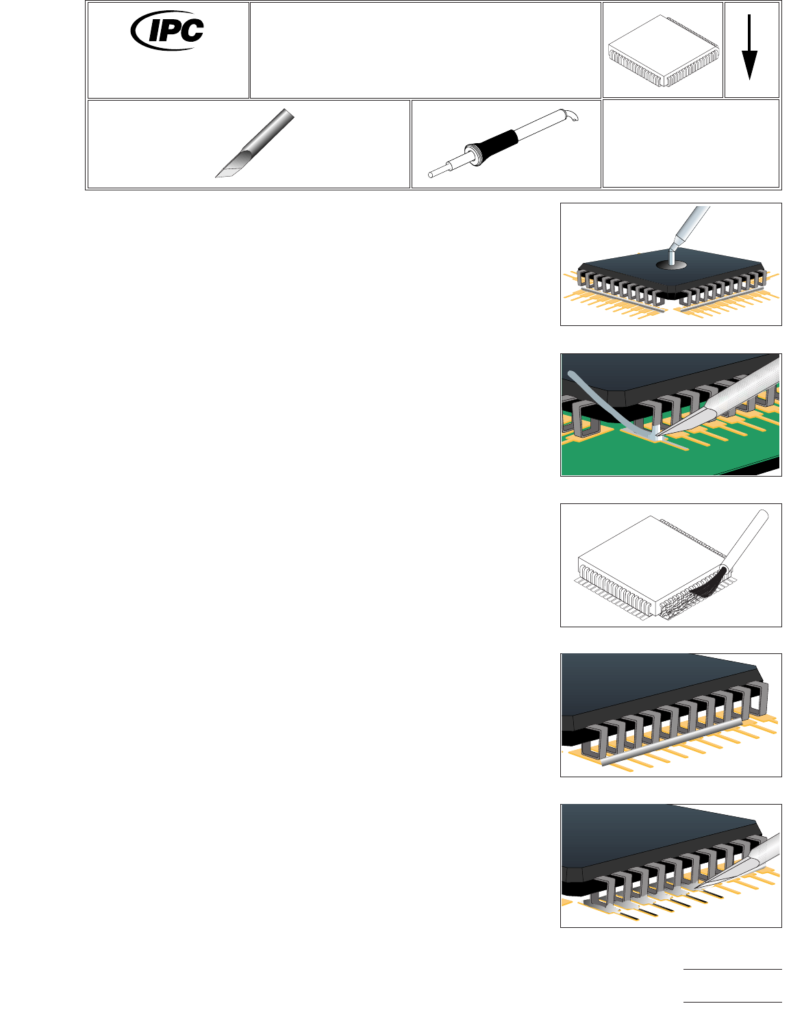
3. Position component ensuring proper lead-to-land alignment. Hold component in
place using the vacuum pick-up tool or tweezers. (See Figure 1.)
4. Apply flux and tack solder opposing corner leads. (See Figure 2.)
5. Apply flux to remaining lead/land areas of the row to be soldered. (See Figure
3.)
6. Cut a piece of flux-cored solder approximately 3/4 the length of one side of the
component.
7. Place the piece of solder onto the lead/land junctions of the side to be soldered.
(See Figure 4.)
8. Clean tip using a damp sponge.
9. Place tip on the first lead/land junction of the side. Observe solder melt. Slowly
move tip along remaining lead/land junctions to form proper solder fillets at each
joint. (See Figure 5.)
10. Repeat steps5-9onremaining sides of component.
11. Re-tin tip.
12. Clean, if required, and inspect.
Figure 1 Position Component
Figure 2 Tack Lead
Figure 3 Apply Flux
Figure 4 Solder Application
Figure 5 Solder Leads
7711A
Rework of
Electronic Assemblies
Revision:
Date: 2/98
J-Lead Installation
Wire Solder Method
Number: 5.6.1
Product Class: R, F, W, C
Skill Level: Advanced
Level of Conformance: High
Material in this manual, IPC-7711 Rework of Electronic Assemblies, was voluntarily established by Technical Committees of
IPC. This material is advisory only and its use or adaptation is entirely voluntary. IPC disclaims all liability of any kind as to the
use, application, or adaptation of this material. Users are also wholly responsible for protecting themselves against all claims
or liabilities for patent infringement. Equipment referenced is for the convenience of the user and does not imply endorsement
by IPC.
Page1of2
Copyright Association Connecting Electronics Industries
Provided by IHS under license with IPC
Not for Resale
No reproduction or networking permitted without license from IHS
--``,``,-`-`,,`,,`,`,,`---