IPC 7711A.pdf - 第68页
NOTES IPC-771 1A Number: 3.2.1 Revision: Date: 2/98 Subject: PGA and Connector Removal P a g e2o f2 Copyright Association Connecting Electronics Industries Provided by IHS under license with IPC Not for Resale No reprodu…
EQUIPMENT REQUIRED
Solder fountain
Chimney or nozzle to match part
Removal tool
Pallet to hold board over fountain
Preheat oven
OPTIONAL EQUIPMENT
Vacuum pick-up tool
MATERIALS
Flux-cored solder
Cleaner
Heat resistant, antistatic gloves
Protective face gear
Heat resistant tape
PROCEDURE
This process is for experienced operators only. Caution must be exercised due to
working with hot, molten solder.
1. Set solder fountain pot control to the required temperature for removing that par-
ticular component from that particular board. Wait until solder pot reaches the set
temperature.
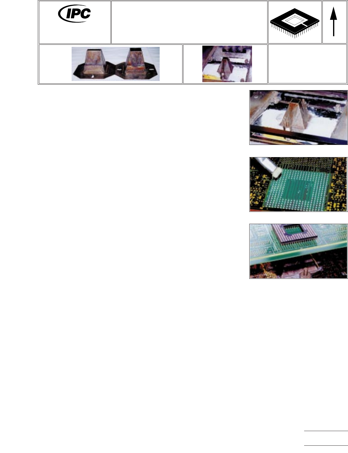
2. Attach the correct nozzle or chimney to the solder pot. (See Figure 1.)
3. Set the timer for the amount of time the fountain is to be running for that particu-
lar part.
4. The area around the rework site may be masked with a high temperature resis-
tant tape, or similar material, to protect the adjacent area during rework. (See
Figure 2.)
5. Preheat the board to the desired temperature, depending on the component
restrictions and the board T
g
material.
6. Flux the bottom side site where the part will be removed. (See Figure 2.)
7. Place the board on the pallet over the solder fountain and trip the timer. (See Fig-
ure 3.)
8. At the end of the timer cycle, use vacuum pickup tool, tweezers, or removal tool
to remove the part from the board.
9. Clean the flux residue, if required, and inspect.
Figure 1 Attach Nozzle
Figure 2 Flux
Figure 3 Place Over Solder Fountain
7711A
Rework of
Electronic Assemblies
Revision:
Date: 2/98
PGA and Connector Removal
Solder Fountain Method
Number: 3.2.1
Product Class: R, F, W, C
Skill Level: Expert
Level of Conformance: Medium
Material in this manual, IPC-7711 Rework of Electronic Assemblies, was voluntarily established by Technical Committees of
IPC. This material is advisory only and its use or adaptation is entirely voluntary. IPC disclaims all liability of any kind as to the
use, application, or adaptation of this material. Users are also wholly responsible for protecting themselves against all claims
or liabilities for patent infringement. Equipment referenced is for the convenience of the user and does not imply endorsement
by IPC.
Page1of2
Copyright Association Connecting Electronics Industries
Provided by IHS under license with IPC
Not for Resale
No reproduction or networking permitted without license from IHS
--``,``,-`-`,,`,,`,`,,`---

NOTES
IPC-7711A
Number: 3.2.1
Revision:
Date: 2/98
Subject: PGA and Connector Removal
Page2of2
Copyright Association Connecting Electronics Industries
Provided by IHS under license with IPC
Not for Resale
No reproduction or networking permitted without license from IHS
--``,``,-`-`,,`,,`,`,,`---
EQUIPMENT REQUIRED
Soldering system
Chip removal tip
Soldering handpiece
OPTIONAL EQUIPMENT
Tweezers
Controllable preheater
MATERIALS
Flux-cored solder
Flux
Cleaner
PROCEDURE
1. Remove conformal coating (if any) and clean work area of any contamination,
oxides or residues.
2. Install the chip removal tip into the soldering handpiece.
3. Start with tip temperature of approximately 315°C and change as necessary.
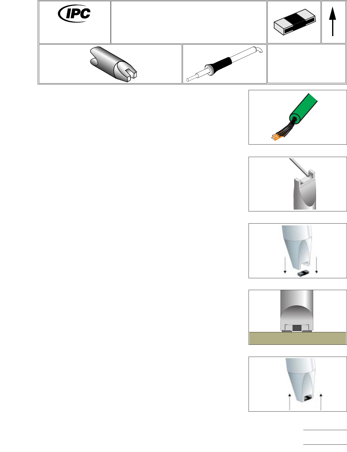
4. Apply flux to all lead/land areas. (See Figure 1.)
5. Remove old solder from tip and thermal shock with a damp sponge.
6. Apply solder to inside of tip forming a crown. (See Figure 2.)
7. Lower tip over component until tip contacts solder joints. (See Figure 3.)
8. Confirm solder melt and lift component from PWB. (See Figures 4 & 5.) (Surface
tension of the tip should lift the component from the board. If this does not
occur, use of tweezers to lift the component is optional.)
NOTE: Chip components may have adhesive between the body and the
board. If adhesive is used, it may be necessary to slightly turn the component
to allow the component to be removed from the board. This must only be
accomplished after complete solder melt to prevent damage.
9. Release component from tip by wiping on a heat resistant surface.
10. Re-tin tip with solder.
11. Prepare lands for component replacement.
Figure 1 Apply Flux
Figure 2 Tin Tips
Figure 3 Position Tip
Figure 4 Melt All Joints
Figure 5 Lift Component
7711A
Rework of
Electronic Assemblies
Revision:
Date: 2/98
Chip Component Removal
Bifurcated Tip
Number: 3.3.1
Product Class: R, F, W, C
Skill Level: Intermediate
Level of Conformance: High
Material in this manual, IPC-7711 Rework of Electronic Assemblies, was voluntarily established by Technical Committees of
IPC. This material is advisory only and its use or adaptation is entirely voluntary. IPC disclaims all liability of any kind as to the
use, application, or adaptation of this material. Users are also wholly responsible for protecting themselves against all claims
or liabilities for patent infringement. Equipment referenced is for the convenience of the user and does not imply endorsement
by IPC.
Page1of2
Copyright Association Connecting Electronics Industries
Provided by IHS under license with IPC
Not for Resale
No reproduction or networking permitted without license from IHS
--``,``,-`-`,,`,,`,`,,`---