IPC 7711A.pdf - 第184页
3. Place the PWA in the system work piece holder. 4. Set hot gas reflow system to achieve the TTP defined by procedural analysis. 5. Perform alignment of gas nozzle to component location (use template, vision system or x…
EQUIPMENT REQUIRED
Hot air or hot gas reflow System (representative examples shown by Figures 1-4)
Gas focusing nozzle (sized to BGA dimensions)
Gas supply (if other than ambient atmosphere)
Preheat method (oven, hotplate, high intensity lamp)
OPTIONAL EQUIPMENT
Bake-out (vacuum, convection) oven
X-ray inspection system
Forced (ambient) air cooling system
Inert gas supply, if used
Microscope/vision system
MATERIALS
Solder paste (paste defined in 1.9.4)
Cleaner
PROCEDURE SUMMARY
The procedure outlined below is generic in nature and identifies the procedural steps
which need be accomplished to effect BGA or CSP installation. Each step must be
tailored to accommodate the attributes and characteristics of the specific system
being used (system manufacturers will customarily provide generalized operating
procedures which must be further refined to achieve optimum results).
PROCEDURAL PRECONDITIONS
The following preconditions shall be accomplished prior to performing the procedure:
1) Develop a time/temperature profile (TTP) for the specific BGA and PWA. (See
1.9, Process Goals and Guidelines.)
NOTE: If plastic body or tape body components are used, see IPC J-STD-
020 (Moisture/Reflow Sensitivity Classification for Plastic Integrated Circuit
Surface Mount Devices) for information on moisture sensitivity classification
tests, preconditioning, and attachment.
2) Bake the PWA to remove entrained moisture which may, if not removed,
precipitate measling or delamination.
PROCEDURE STEPS
NOTE: Some systems do not include integrated preheating capability and it may
be necessary to preheat the PWA and BGA separately.
1. Clean PWA surface and lands.
2. Apply solder paste (stencil, screen, dot dispense, as appropriate).
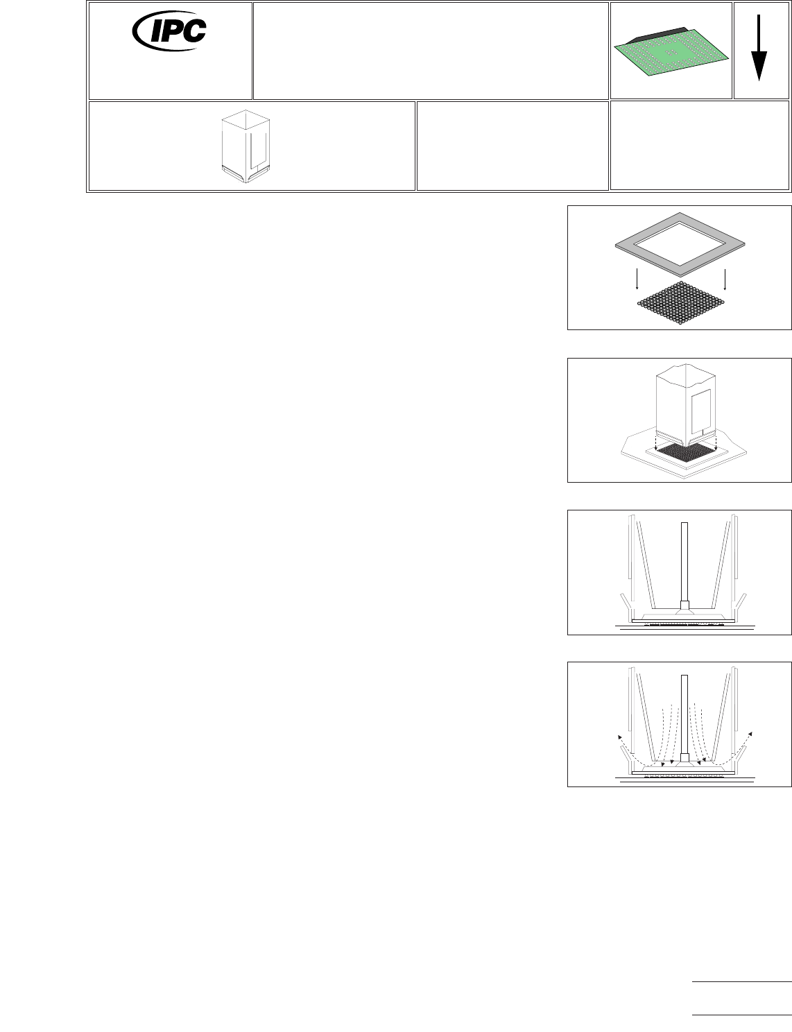
Figure 1 Align Template
Figure 2 Align Nozzle
Figure 3 Ball/Land Contact
Figure 4 Begin Reflow
7711A
Rework of
Electronic Assemblies
Revision:
Date: 2/98
BGA/CSP Installation
Using Solder Paste to Prefill Lands
Number: 5.7.2
Product Class: R,F,W,C
Skill Level: Advanced
Level of Conformance: High
Material in this manual, IPC-7711 Rework of Electronic Assemblies, was voluntarily established by Technical Committees of
IPC. This material is advisory only and its use or adaptation is entirely voluntary. IPC disclaims all liability of any kind as to the
use, application, or adaptation of this material. Users are also wholly responsible for protecting themselves against all claims
or liabilities for patent infringement. Equipment referenced is for the convenience of the user and does not imply endorsement
by IPC.
Page1of2
Copyright Association Connecting Electronics Industries
Provided by IHS under license with IPC
Not for Resale
No reproduction or networking permitted without license from IHS
--``,``,-`-`,,`,,`,`,,`---

3. Place the PWA in the system work piece holder.
4. Set hot gas reflow system to achieve the TTP defined by procedural analysis.
5. Perform alignment of gas nozzle to component location (use template, vision
system or x-y locator as available/appropriate).
6. Using component placement aids available (vacuum placement pick, x-y loca-
tor, etc.), place BGA onto land area while observing indexing/keying indicators
to assume proper theta orientation.
7. Bring gas focusing nozzle into reflow position and accomplish fine alignment.
8. Perform TTP reflow cycle defined by procedural analysis.
9. Perform accelerated cooling cycle if appropriate.
10. Clean PWA as appropriate to customer requirements.
11. Perform x-ray inspection of PWA if appropriate.
IPC-7711A
Number: 5.7.2
Revision:
Date: 2/98
Subject: BGA/CSP Installation Using Solder Paste to Prefill Lands
Page2of2
Copyright Association Connecting Electronics Industries
Provided by IHS under license with IPC
Not for Resale
No reproduction or networking permitted without license from IHS
--``,``,-`-`,,`,,`,`,,`---
EQUIPMENT REQUIRED
Solder removal system
Convective reflow station
Reballing fixture
OPTIONAL EQUIPMENT
Reflow oven
Bake-out (vacuum, convection) oven
MATERIALS
Flux
Cleaner
Tissue/wipes
Solder spheres
NOTE
Moisture sensitive components (as classified by IPC/JEDEC J-STD-020 or equivalent
documented procedure) must be handled in a manner consistent with J-STD-033 or
an equivalent documented procedure.
CAUTION
Verify component can withstand the multiple reflow cycles.
PROCEDURE
1. Remove excess solder in accordance with procedures 4.1.2, 4.1.3, or 4.2.1
2. Clean and inspect BGA for coplanarity.
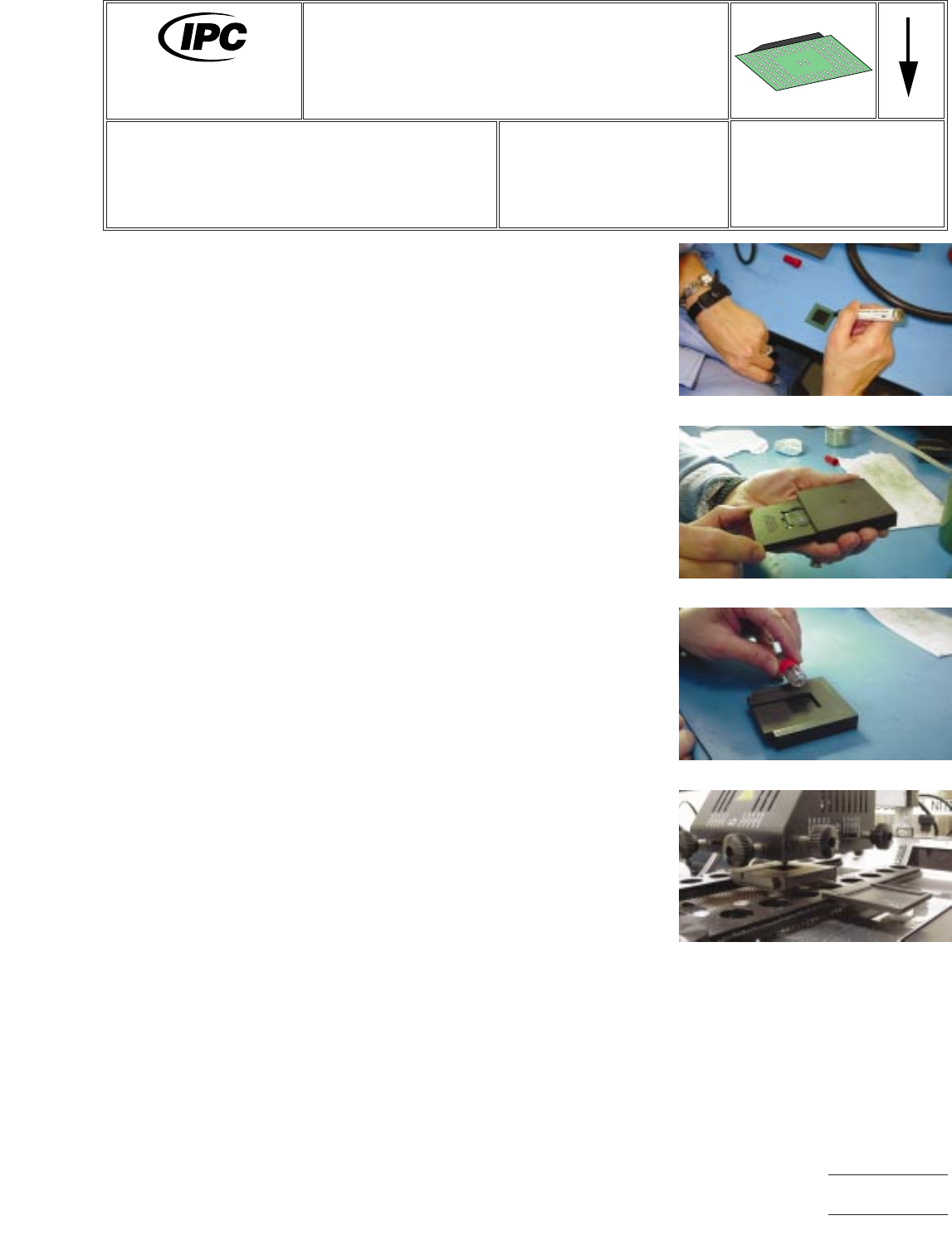
3. Apply flux to land on BGA. (Figure 1.)
4. Insert the BGA into the applicable reballing fixture and secure. (Figure 2.)
5. Carefully pour solder sphere into fixture. (Figure 3.)
6. Drain off all excess spheres. Ensure all holes in fixture have a solder sphere.
7. Reflow solder spheres using the established profile. (Figure 4.)
8. Allow BGA to cool and remove from fixture.
9. Clean (if necessary) and inspect the BGA.
Figure 1
Figure 2
Figure 3
Figure 4
7711A
Rework of
Electronic Assemblies
Revision:
Date: 5/02
BGA Reballing Procedure
Number: 5.7.3
Product Class: R, C
Skill Level: Advanced
Level of Conformance: High
Material in this manual, IPC-7711 Rework of Electronic Assemblies, was voluntarily established by Technical Committees of
IPC. This material is advisory only and its use or adaptation is entirely voluntary. IPC disclaims all liability of any kind as to the
use, application, or adaptation of this material. Users are also wholly responsible for protecting themselves against all claims
or liabilities for patent infringement. Equipment referenced is for the convenience of the user and does not imply endorsement
by IPC.
Page1of2
Copyright Association Connecting Electronics Industries
Provided by IHS under license with IPC
Not for Resale
No reproduction or networking permitted without license from IHS
--``,``,-`-`,,`,,`,`,,`---