IPC 7711A.pdf - 第194页
NOTES IPC-771 1A Number: 6.1.4 Revision: Date: 2/98 Subject: Removing Shorts Between Gull Wing P a g e2o f2 Copyright Association Connecting Electronics Industries Provided by IHS under license with IPC Not for Resale No…
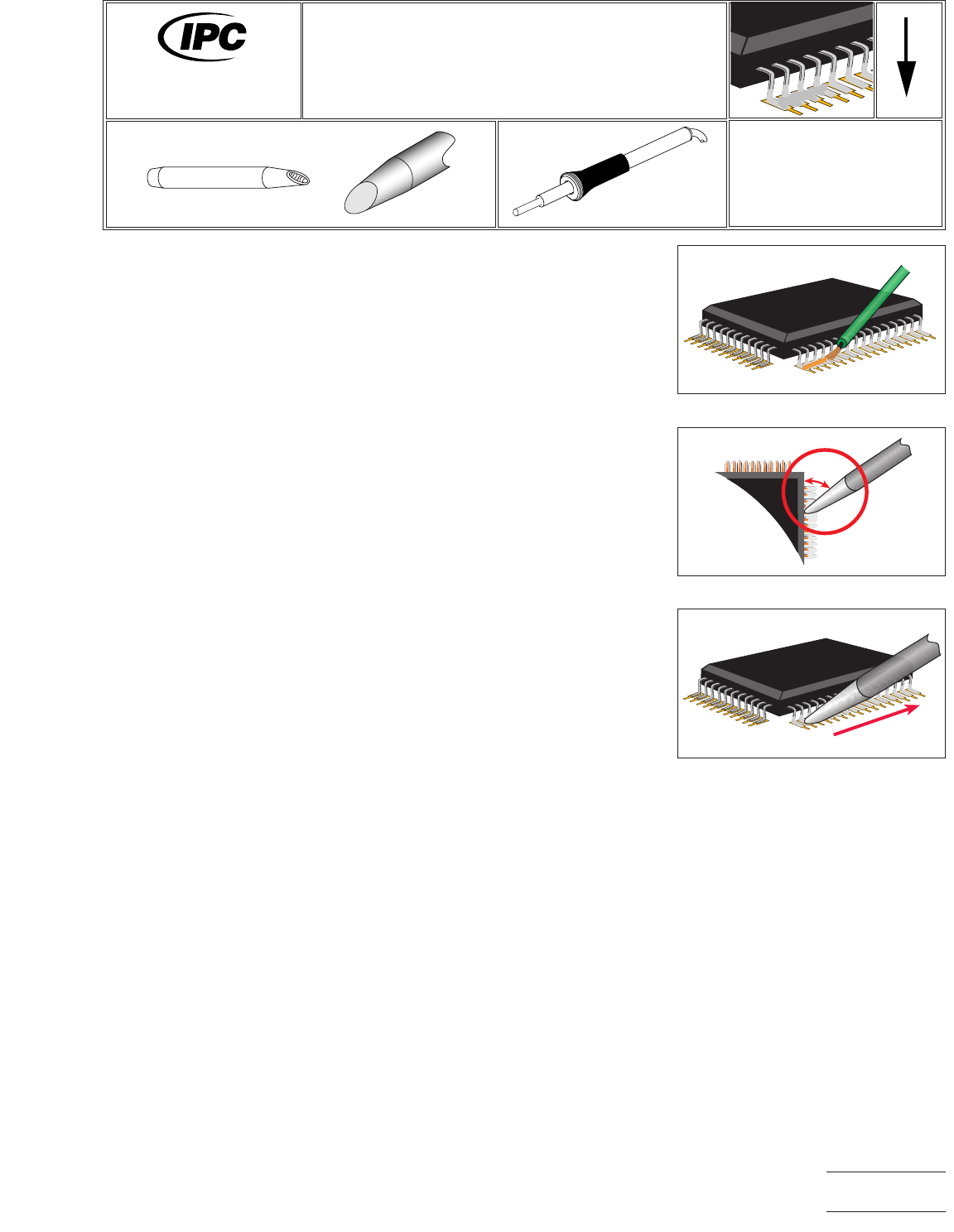
EQUIPMENT REQUIRED
Soldering system
Soldering iron
Cup of flat faced tip
MATERIALS
Flux
PROCEDURE
1. Install appropriate tip.
2. Start with the coolest tip temperature possible (approximately 315°C) and change
as necessary. The surface attraction of the solder to the tip must overcome that
of the leads.
3. Clean tip using a damp sponge.
4. Apply flux to the bridged leads. (See Figure 1.)
5. Hold the tip so the toe of the hoof runs parallel to the row of leads, that is, the
side of the tip toward the side of the component. The angle between the side of
the tip and the side of the component would ideally be zero for maximized heat
transfer, but can be up to 30° depending on operator preference. (See Figure 2.)
6. Bring the tip face down flat onto the bridge and pause for reflow. Draw the tip,
and the liquid bridge with it, down the row of leads, respreading the solder across
the rest of the leads. (See Figure 3.)
7. Clean, as required, and inspect.
Figure 1 Apply Flux
Figure 2 Hold Tip Parallel
30 degree
maximum
Figure 3 Draw Tip Down Row
7711A
Rework of
Electronic Assemblies
Revision:
Date: 2/98
Removing Shorts Between Gull Wing
Respread Method
Number: 6.1.4
Product Class: R, F, W, C
Skill Level: Intermediate
Level of Conformance: High
Material in this manual, IPC-7711 Rework of Electronic Assemblies, was voluntarily established by Technical Committees of
IPC. This material is advisory only and its use or adaptation is entirely voluntary. IPC disclaims all liability of any kind as to the
use, application, or adaptation of this material. Users are also wholly responsible for protecting themselves against all claims
or liabilities for patent infringement. Equipment referenced is for the convenience of the user and does not imply endorsement
by IPC.
Page1of2
Copyright Association Connecting Electronics Industries
Provided by IHS under license with IPC
Not for Resale
No reproduction or networking permitted without license from IHS
--``,``,-`-`,,`,,`,`,,`---

NOTES
IPC-7711A
Number: 6.1.4
Revision:
Date: 2/98
Subject: Removing Shorts Between Gull Wing
Page2of2
Copyright Association Connecting Electronics Industries
Provided by IHS under license with IPC
Not for Resale
No reproduction or networking permitted without license from IHS
--``,``,-`-`,,`,,`,`,,`---

8.1 Splicing
1. THE PROCESS OF WIRE SPLICING IS USED IN TWO
CASES:
a. When a self-lead component (inductor, transformer,
choke, etc.) is installed (either during assembly or
as a replacement for a failed component) and,
b. In the process of repairing a damaged wire when
removal and replacement of the entire wire length
is not feasible.
2. THE FOUR MOST COMMON SPLICES USED ARE:
• Mesh Splices Mesh splices require the least wire
length in order to complete the splice and result in a
splice diameter only slightly larger than the diameter
of the wire used.
• Wrap Splices Wrap splices require a longer wire
length in order to complete the splice and have a
splice diameter equal to three times the diameter of the
wire used.
• Hook Splices Hook Splices require the most wire
length in order to complete the splice and have a
splice diameter equal to three times the diameter of the
wire used.
• Lap Splices Lap splices, like mesh splices, require a
minimal amount of original wire length and may be
used to perform repair of a damaged wire when:
a. Sufficient slack is available in the wire to achieve
the necessary overlap, and
b. The repaired wire will not be subjected to longitu-
dinal stress after repair.
3. WIRE SPLICING
Locating/Isolating Damage Locate the damaged
wire. If the wire is broken, determine if both sections
are available. Isolate the damaged area by using point-
to-point resistance measurements.
Note: If the wire was broken (separated) by a cutting
action, the cut ends can be spliced at the point of
breakage/separation. If the wire was broken (separated)
by a pulling action, e.g., stretching or pulling until sepa-
ration, then the wire strands on both sides of the break
will have suffered hidden mechanical damage in the
form of stretching, elongation and reduction of indi-
vidual strand diameter. In such cases, where separation
was caused by a pulling action, it is desirable to remove
(cut-out) wire which could have been damaged by
stretching and installing a longer splice than would nor-
mally be used.
4. FEASIBILITY OF REPAIR
Prior to repairing damaged wires, the following consid-
erations must be made:
• Should damaged wires be replaced in their entirety
• Should wires be repaired using solder sleeves
• If complete replacement is not feasible, determine if
one section of wire may be replaced thereby limiting
the number of splices to one
• If no section of the damaged wire can be replaced,
splice in a replacement section of wire with two
splices
5. INSULATED CONDUCTOR STRIPPING
Insulated conductors should be stripped a distance
longer than required for the solder connection. This
allows for easier forming of the conductor. The excess
conductor shall be trimmed off prior to soldering. The
following stripping methods are recommended.
a. Thermal wire strippers are to be used on insula-
tions that will melt upon application of heat. This
method is preferred because it minimizes the pos-
sibility of conductor damage.
Caution: Do not use mechanical strippers on wire
smaller than AWG-20, as the strippers may stretch the
wire.
b. Mechanical strippers are to be used on insulations
that cannot be thermally stripped. This method
does not apply to enamel insulation.
c. Chemical stripper is used on conductors that have
an enamel/varnish coating for insulation.
1) Follow the manufacturer’s instructions on the
length of time for the chemical reaction to take
place.
2) The stripper may have to be neutralized. Follow
the manufacturer’s safety precautions on both
equipment and personnel.
Warning: Chemical strippers contain ingredients
harmful to both skin and eyes. Prescribed protective
clothing, including industrial goggles/spectacles, shall
be worn when opening the container and during use. If
stripper gets on skin, wash immediately with fresh
water and soap and rinse freely. If stripper gets into
eyes, flood with large quantity of fresh water. Do not
apply ointments or salve, obtain medical aid at once.
Follow manufacturer’s safety instructions.
October 2003 IPC-7711A
1
Copyright Association Connecting Electronics Industries
Provided by IHS under license with IPC
Not for Resale
No reproduction or networking permitted without license from IHS
--``,``,-`-`,,`,,`,`,,`---