IPC 7711A.pdf - 第315页
T able 1 Jumper Wire T ermination Methods Figure T ype Wire T ermination Method Acceptability 7 PTH Hole Wire soldered into plated-through hole on component side. * Acceptable 8 PTH Lead Wire soldered parallel to lead on…

CAUTION
The insulation shall not be stripped back more than two wire diameters from the
solder joint. Wire insulation may touch but not penetrate the solder joint provided
proper wetting of the wire is evident.
3. Bend the wire as needed and run the wire along board surface. Route the jumper
wire using the shortest route in an XY direction with the fewest possible bends to
the second termination point.
NOTE
Jumper wires shall not be routed under or over component leads or component
bodies. Contact with heat sinks must be avoided.
CAUTION
Do not bend the wire tighter than a radius of three times the conductor diameter.
4. After routing the jumper wire, solder the opposite end. Clean if necessary.
CAUTION
Wires soldered to lifted or clipped components leads may require insulation to
prevent shorting.
JUMPER WIRE BONDING
1. After the wire has been soldered at both ends and cleaned if necessary, the wire
should be bonded to the board surface.
NOTE
Bonding is not required if wire is insulated and insulated length is less than 25 mm
[1.00 in].
2. Bond the jumper wire using one of the following methods.
A. Tape Dots or Tape Strips. (See Figure 4.)
B. Quick Set Adhesive. (See Figure 5.)
C. Hot Melt Adhesive. (See Figure 5.)
D. Hot Bonding. Some jumper wires are manufactured with a special thermo-set
adhesive coating and are thermally bonded to the board surface with a spe-
cial bonding tool. (See Figure 6.)
3. Bond the jumper wire within 6.0 mm [0.25 in] of each solder joint.
4. Bond the jumper wire within 6.0 mm [0.25 in] of each bend in the wire.
5. Bond the jumper wire at intervals not less than 25 mm [1.00 in] on straight runs.
IPC-7721A
Number: 6.1
Revision:
Date: 11/99
Subject: Jumper Wires
Page4of10
Copyright Association Connecting Electronics Industries
Provided by IHS under license with IPC
Not for Resale
No reproduction or networking permitted without license from IHS
--``,``,-`-`,,`,,`,`,,`---
Table 1 Jumper Wire Termination Methods
Figure Type Wire Termination Method Acceptability
7 PTH Hole Wire soldered into plated-through hole on component side. * Acceptable
8 PTH Lead Wire soldered parallel to lead on component side. Acceptable
9 PTH Hole Wire soldered into plated-through hole on solder side. * Acceptable
10 PTH Hole Wire wrapped around component lead on solder side. Acceptable
11 PTH Hole Wire wrapped around lead on component side. Acceptable
12 PTH Lead Wire soldered to lifted component lead. + Acceptable
13 PTH Lead Wire soldered to clipped lead on component side. + Acceptable
14 PTH Lead Wire looped and soldered to adjacent component leads. Acceptable
15 PTH Lead Wire soldered to lead, wire over component. Not Recommended
16 PTH Lead Soldered perpendicular to component lead. Not Recommended
17 PTH Lead Multiple wires soldered to component lead overhanging edge. Not Recommended
18 Chip Wire soldered to pad, parallel or perpendicular to component. Acceptable
19 Chip Wire soldered parallel or perpendicular to component. Acceptable
20 Chip Wire soldered to component end, lifted off pad. Acceptable
21 Chip Multiple wires overhanging pad edge. Not Recommended
22 PTH Hole Wire soldered into plated-through hole. * Acceptable
23 PTH Pad Wire soldered across top of PTH pad. Acceptable
24 PTH Pad Multiple wires soldered to pad overhanging pad edge. Not Recommended
25 Conductor Wire soldered parallel to conductor, contact, SMT pad. Acceptable
26 Conductor Wire perpendicular to conductor, contact, SMT pad. Not Recommended
27 Conductor Multiple wires soldered to conductor, contact, SMT pad. Not Recommended
28 J Lead Wire soldered parallel to component lead. Acceptable
29 J Lead Wire soldered to clipped component lead. + Acceptable
30 J Lead Wire looped and soldered to adjacent component leads. Acceptable
31 J Lead Wire soldered to component lead, wire running over component. Not Recommended
32 J Lead Wire soldered perpendicular to lead. Not Recommended
33 J Lead Multiple wires soldered to lead overhanging edge. Not Recommended
34 J Lead Wire soldered to lifted component lead. Not Recommended
35 Gull Wing Wire soldered parallel to component lead. Acceptable
36 Gull Wing Wire soldered to lifted component lead. + Acceptable
37 Gull Wing Wire soldered to clipped component lead. + Acceptable
38 Gull Wing Wire looped and soldered to adjacent component leads. Acceptable
39 Gull Wing Wire soldered to component lead, wire over component. Not Recommended
40 Gull Wing Wire soldered perpendicular to component lead. Not Recommended
41 Gull Wing Multiple wires soldered to lead overhanging edge. Not Recommended
* Jumper wires soldered into plated-through holes must be discernible on the opposite side.
+ Jumper wires soldered to lifted or clipped component leads may require insulation to prevent shorting.
IPC-7721A
Number: 6.1
Revision:
Date: 11/99
Subject: Jumper Wires
Page5of10
Copyright Association Connecting Electronics Industries
Provided by IHS under license with IPC
Not for Resale
No reproduction or networking permitted without license from IHS
--``,``,-`-`,,`,,`,`,,`---
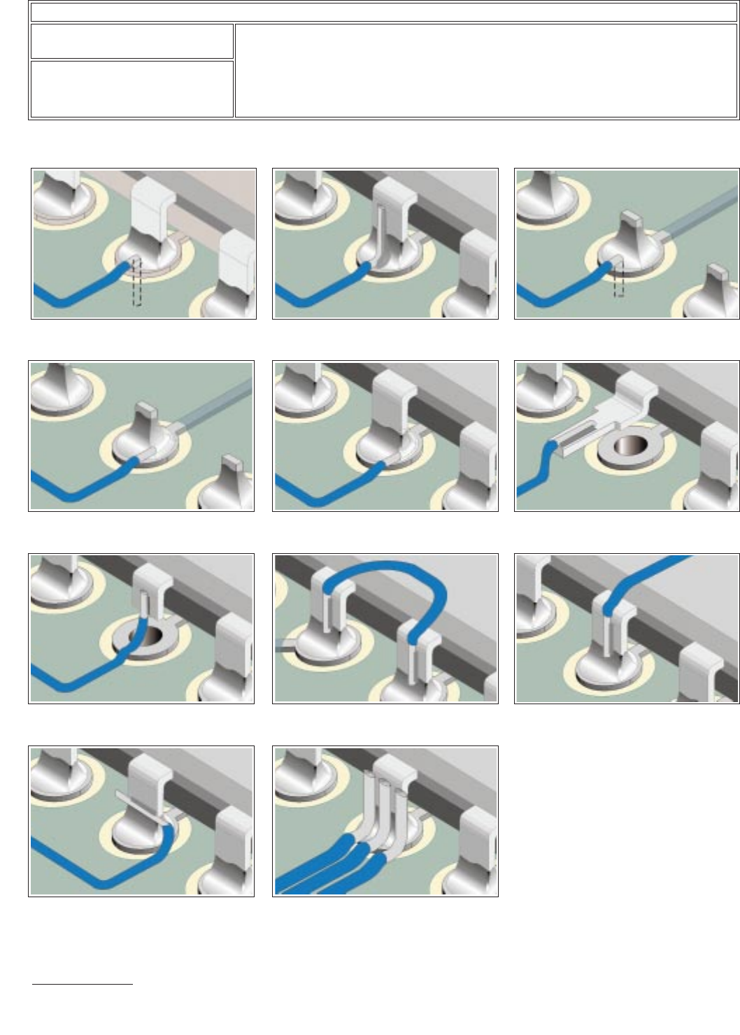
Jumper Wire Termination Figures – Through-Hole Components
* Jumper wires soldered into plated-through holes must be discernible on the opposite side.
+ Jumper wires soldered to lifted or clipped component leads may require insulation to prevent shorting.
Figure 7
Acceptable
Wire soldered into
plated-through hole, component side. *
Figure 10
Acceptable
Wire wrapped
around component lead on solder side.
Figure 13
Acceptable
Wire soldered to
clipped lead on component side. +
Figure 16
Not Recommended
Soldered
perpendicular to component lead.
Figure 8
Acceptable
Wire soldered
parallel to lead on component side.
Figure 11
Acceptable
Wire wrapped
around lead on component side.
Figure 14
Acceptable
Wire looped and
soldered to adjacent component leads.
Figure 17
Not Recommended
Multiple
wires soldered to lead overhanging edge.
Figure 9
Acceptable
Wire soldered into
plated-through hole on solder side. *
Figure 12
Acceptable
Wire soldered to
lifted component lead. +
Figure 15
Not Recommended
Wire
soldered to lead, wire over component.
IPC-7721A
Number: 6.1
Revision:
Date: 11/99
Subject: Jumper Wires
Page6of10
Copyright Association Connecting Electronics Industries
Provided by IHS under license with IPC
Not for Resale
No reproduction or networking permitted without license from IHS
--``,``,-`-`,,`,,`,`,,`---