IPC 7711A.pdf - 第331页
OUTLINE This method is used to replace damaged or missing conductors on the flexible printed wiring surface. CAUTION Flexible laminates come in a variety of materials, e.g., Mylar®, Teflon®, and Kap- ton®. These laminate…
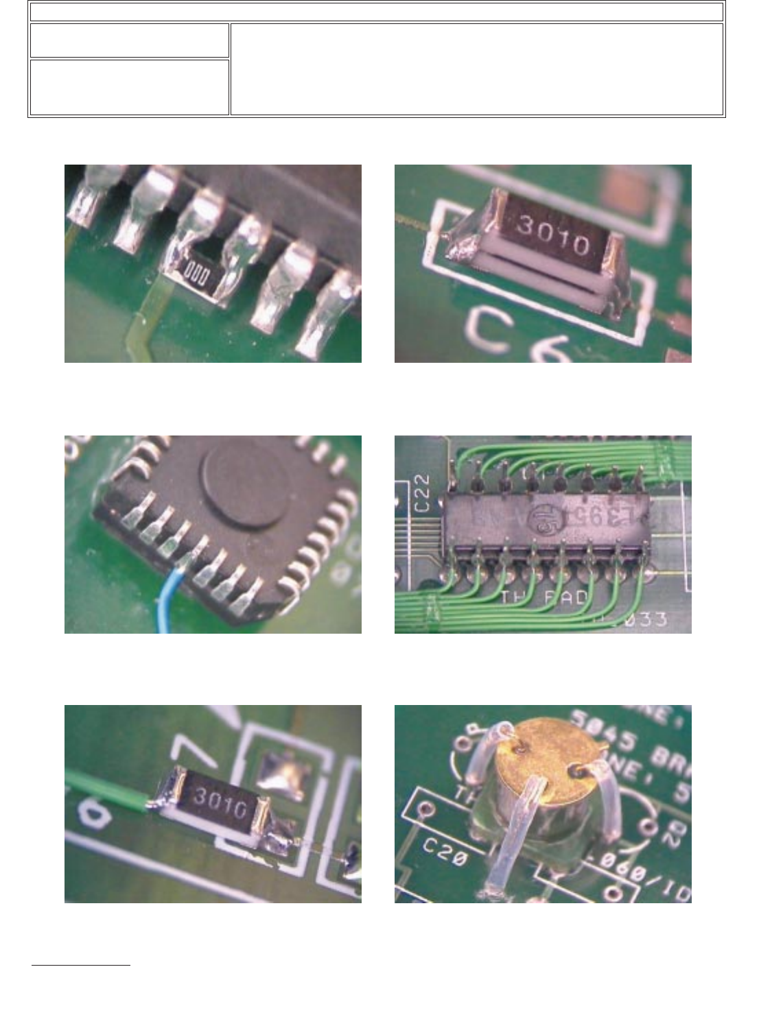
Component Modification Examples (continued)
Figure 7 Chip component bridging leads of surface
mount component.
Figure 8 Chip component stacked onto another chip
component.
Figure 9
Acceptable
Surface mount component
mounted upside down with jumper wires attached.
Note: One lead is bent outward.
Figure 10 DIP component mounted upside down with
jumper wires attached.
Figure 11 Chip component mounted to one pad only. Figure 12 Radial lead component mounted upside
down. Note: Insulate leads to avoid contact with
component body.
IPC-7721A
Number: 6.3
Revision:
Date: 03/01
Subject: Component Modifications and Additions
Page4of4
Copyright Association Connecting Electronics Industries
Provided by IHS under license with IPC
Not for Resale
No reproduction or networking permitted without license from IHS
--``,``,-`-`,,`,,`,`,,`---
OUTLINE
This method is used to replace damaged or missing conductors on the flexible
printed wiring surface.
CAUTION
Flexible laminates come in a variety of materials, e.g., Mylar®, Teflon®, and Kap-
ton®. These laminates are easily damaged during repair, if correct procedures are
not used.
REFERENCES
2.1 Handling Electronic Assemblies
2.2 Cleaning
TOOLS & MATERIALS
Dental Mixing Slab
Scalpel Blade
Pumice Impregnated Wheel
Dental Tool (Carver)
Dental Tool (Chisel)
Soldering Iron
Isopropyl Alcohol
Acid Brush
Oven
Scalpel
Microscope
Rotary Bristle Brush
Tweezers
Orangewood Stick
Soldering Iron Tip
Lint-Free Tissue
Silicone Resin
Amber Colored Polyimide Film
PROCEDURE
1. After the damaged area has been isolated, mark the area of the laminate that is
to be removed.
NOTE
Only enough laminate should be removed to expose the needed work area.
2. Support the flexible laminate with a flat, smooth surface such as a dental mixing
slab or a piece of stainless steel. A firm base will keep the assembly from mov-
ing while repairing the damaged area.
WARNING
Do not apply lateral pressure to the scalpel. The blade could snap and cause
personal injury.
To ensure personnel safety and prevent workpiece damage, spot tools under the
microscope in the work area before looking through the microscope.
CAUTION
Excessive pressure with a removal tool can cause additional damage to the lami-
nate.
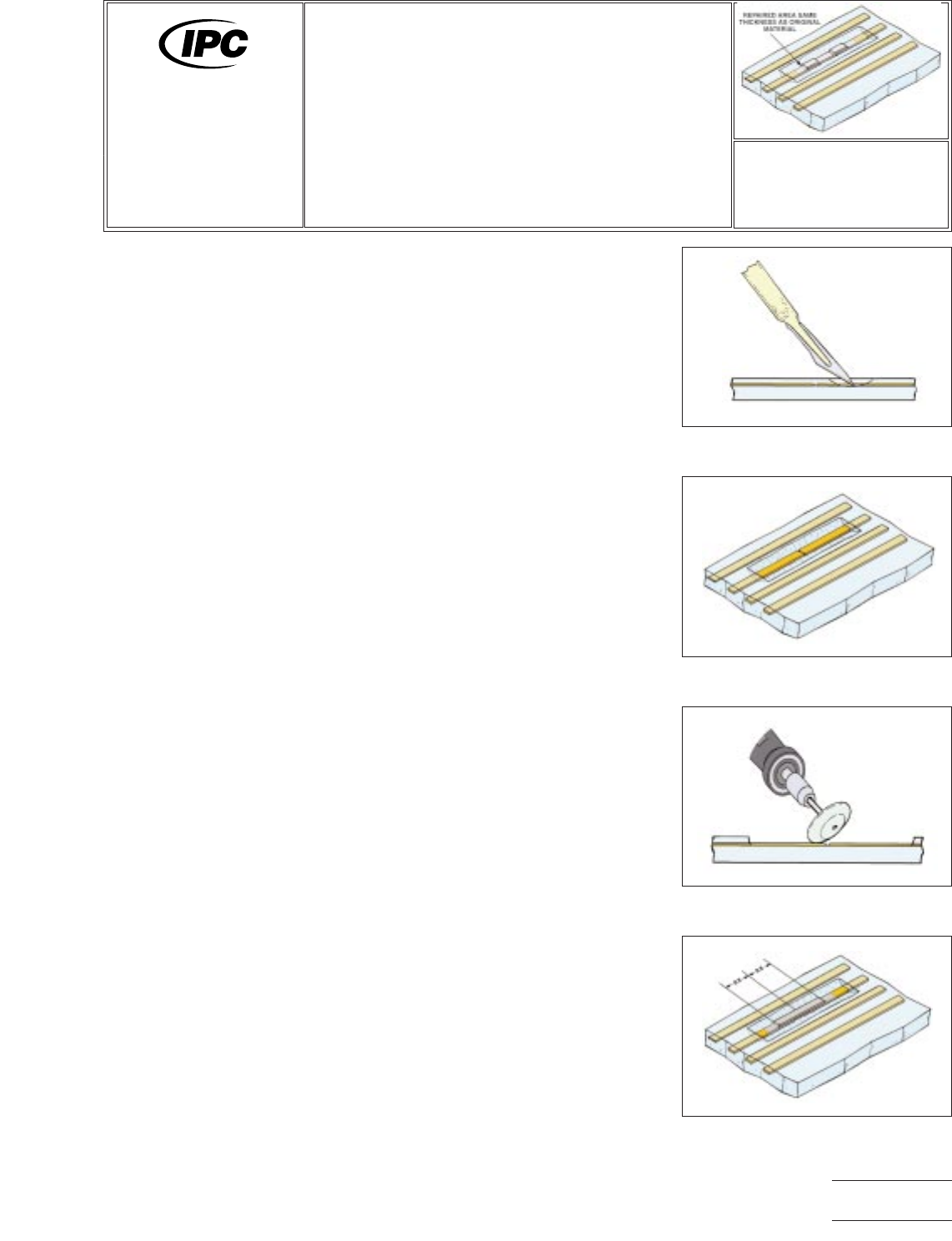
Figure 1 Laminate removal.
Figure 2 Laminate removed.
Figure 3 Adhesive removal.
Figure 4 Conductor hairline crack
repair.
7721A
Repair and
Modification of
Printed Boards and
Electronic Assemblies
Revision:
Date: 10/03
Flexible Conductor Repair
Number: 7.1.1
Product Class: F
Skill Level: Expert
Level of Conformance: Medium
Material in this manual was voluntarily established by Technical Committees of IPC. This material is advisory only and its use
or adaptation is entirely voluntary. IPC disclaims all liability of any kind as to the use, application, or adaptation of this material.
Users are also wholly responsible for protecting themselves against all claims or liabilities for patent infringement. Equipment
referenced is for the convenience of the user and does not imply endorsement by IPC.
Page1of4
Copyright Association Connecting Electronics Industries
Provided by IHS under license with IPC
Not for Resale
No reproduction or networking permitted without license from IHS
--``,``,-`-`,,`,,`,`,,`---
3. Remove the laminate around the damaged conductor by working on the thin-
nest side of the flexible conductor. Laminate can be removed by using a light
abrasive such as a pumice-impregnated wheel or rotary bristle brush. Removal
may also be accomplished by cutting with a scalpel or dental tool. (See Figure
1.)
NOTE
Placing the microscope at an angle of 10°-30° to the flexible laminate may aid
in determining the depth of the laminate removal.
4. Cut the laminate at a 45° angle along the bottom edge of the damaged con-
ductor. Ends of laminate should be cut out at a 90° angle perpendicular to the
conductor. The length of the laminate removed shall allow a minimum of 1/2
inch (1.3 cm) overlap on both sides of the damaged conductor area plus room
for the end fillets on both sides of the replacement conductor. (Laminate
Removal = Damaged Area + End Fillets + 1 inch (2.5 cm).) (See Figure 2.)
5. In many instances an adhesive will be coated onto the conductors. This must
also be removed from the area where the replacement conductor is going to
overlap the original conductor. The adhesive can be removed using light abra-
sion such as an ink eraser or rotary bristle brush or abrasive wheel. (See Figure
3.)
6. If conductor is not damaged and only the laminate requires replacement, pro-
ceed to step 18.
7. Once the laminate has been removed, the method of repair must be deter-
mined.
8. For a hairline crack, the repair will consist of a lap replacement with no original
conductor material removed. (See Figure 4.)
9. For more extensive damage, the damaged conductor will have to be removed
and a replacement conductor lap soldered in place. Any damaged portions of
the conductor shall be removed using the following method:
CAUTION
Exercise care when using a scalpel and tweezers to prevent damage to an
adjacent conductor.
10. Using a scalpel or dental chisel, bevel cut the conductor approximately 45° just
outside the damaged area on both sides. (In order to have at least 1/2 inch (1.3
cm) of original conductor exposed, additional laminate material may have to be
removed on both sides).
11. Grasp the damaged conductor with tweezers and remove. (See Figure 5.)
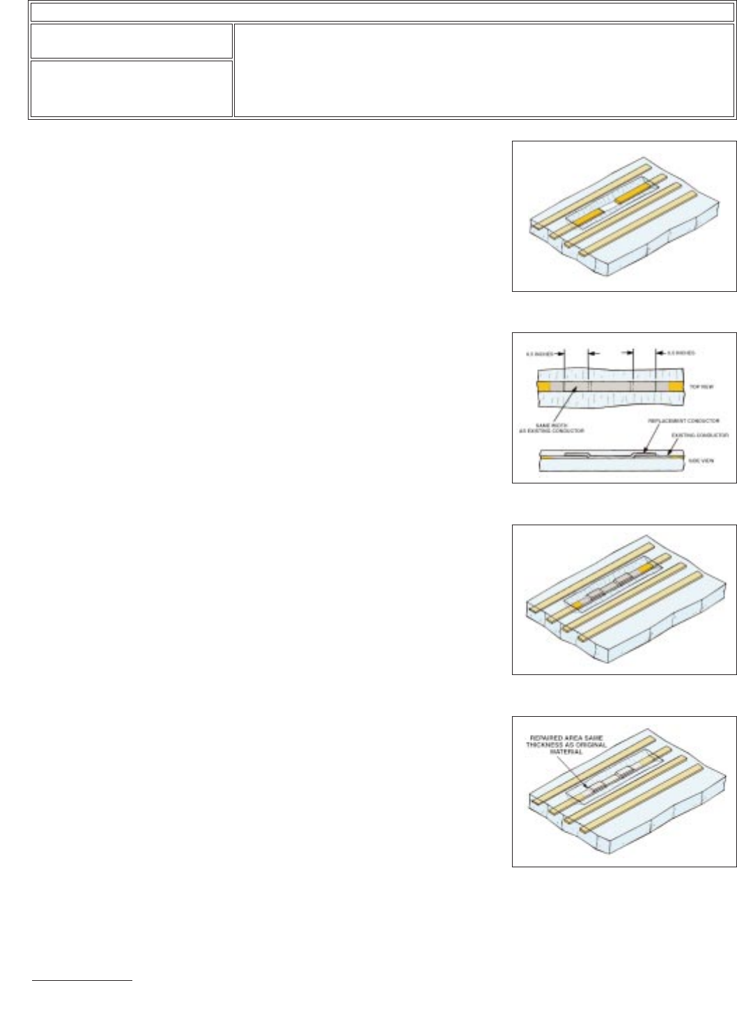
12. Obtain a replacement conductor equal to or slightly greater in width and thick-
ness and a minimum of 1 inch (2.5 cm) longer than the removed damaged con-
ductor. (See Figure 6 top.)
NOTE
All adhesive must be removed from the replacement conductor to ensure good
wetting action.
Figure 5 Beveling.
Figure 6 Replacement specifications.
Figure 7 Replacement conductor
soldered.
Figure 8 Repair encapsulated.
IPC-7721A
Number: 7.1.1
Revision:
Date: 10/03
Subject: Flexible Conductor Repair
Page2of4
Copyright Association Connecting Electronics Industries
Provided by IHS under license with IPC
Not for Resale
No reproduction or networking permitted without license from IHS
--``,``,-`-`,,`,,`,`,,`---