DECAN_S2_Operation(ENG_Ver4.1).pdf - 第27页
DE CAN S2 O pe rat ion H an db ook 3-8 Chap ter 3 This chapter describes the production procedure. Pr oduction Advanced Chip Shooter Pr epara tion F or Oper atio n Ⅰ > N ozzl e ty pe and appli ed par t Preparation F o…
DECAN S2 Operation Handbook
3-7
Chapter 3
This chapter describes the production procedure.
Production
Advanced Chip Shooter
Preparation For Operation Ⅰ > Nozzle type and applied part
Preparation For Operation Ⅰ
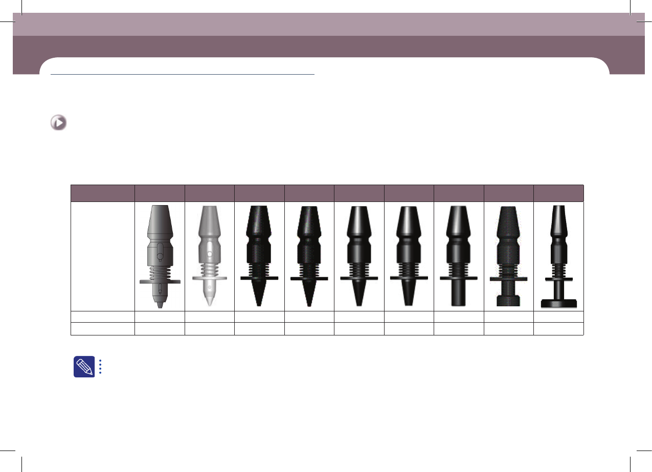
6. Type of nozzle(S2)
Nozzle Name CN015 CN020 CN030 CN040 CN065 CN140 CN220 CN400 CN110
External shape
Outside diameter Φ 0.38 Φ 0.5 Φ 0.6 Φ 0.75 Φ 1.2 Φ 2.2 Φ 3.6 Φ 6.0 Φ 12.7
Inside diameter Φ 0.13 Φ 0.16 Φ 0.28 Φ 0.38 Φ 0.65 Φ 1.4 Φ 2.2 Φ 4.0 Φ 11.0
ㆍ Select the appropriate nozzle according to the type and size of the part to be placed.
For a detailed description of how to check and clean the nozzle, please refer to “Chapter 2 Daily Inspection” in the maintenance handbook.
DECAN S2 Operation Handbook
3-8
Chapter 3
This chapter describes the production procedure.
Production
Advanced Chip Shooter
Preparation For Operation Ⅰ > Nozzle type and applied part
Preparation For Operation Ⅰ
Production
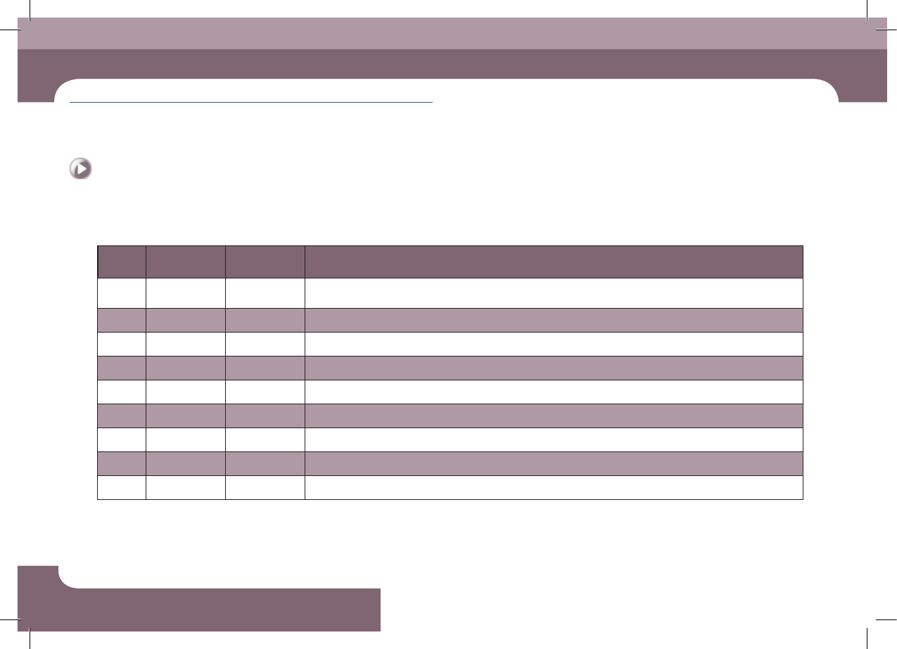
7. Nozzle type and applied part(S2)
Nozzle
Name
Material
number
Minimum part
width
Applied part
CN015
AM03-
013641A
0.15~0.4 03015 Chip Dedicated
CN020 J90551006A 0.2~0.50 0402 Chip Dedicated
CN030 J9055133C 0.3 ~ 1.5 0603 Chip Dedicated
CN040 J9055134C 0.5 ~ 1.25 1005 ~ 1608 Chip Dedicated
CN065 J9055136C 0.8 ~ 2.5 1608, 2012, 3216, Melf, Hemt, SSOP03, TR(23), TR2, Chip- Tantal(3012)
CN220 J9055351A 4.0 ~ 7.0 3216, 6432, Chip-Aluminum(5753), Chip-Tantal(7343), TR(13), Trimmer, SOP2(04), SOP(48), SSOP08
CN220 J9055351A 4.0 ~ 7.0 Chip-Aluminum(7268), SOP(48), Connector, QFP(48), Chip-Coil(8280), Chip-Tantal(8060)
CN400 J90551072A 7.0 ~ 10.0 Chip-Aluminum (9082), SOP(66), SOP2(50), QFP(44), PLCC(18), SOJ2, Connector, TR(22), BGA (208G), Chip-Coil(1212)
CN110 J9055260B 20.0 ~ QFP (Large), PLCC (Large)
ㆍ Select the appropriate nozzle according to the type and size of the part to be placed.
DECAN S2 Operation Handbook
3-9
Chapter 3
This chapter describes the production procedure.
Production
Advanced Chip Shooter
Preparation For Operation Ⅰ > Install feeder/nozzle and order parts
Preparation For Operation Ⅰ
3. Install feeder/nozzle and order parts
1. Check feeder arrangement and install feeders
Step 1.
Secure the feeder in the corresponding slot
Step 2.
Secure the grip
A feeder must be installed as set in the 'Feeder' of the 'PCB Edit'
menu. The method to check whether the feeder is installed correctly
is as follows.
ㆍ The user checks the slot number and part information one by one
manually.
ㆍ When using an IT feeder system, an incorrect feeder insertion can
be checked automatically.
When incorrect feeder insertion occurs, the feeder LED blinks red and
an error message is displayed in the MMI screen. For more details
about the IT feeder system, refer to the corresponding manual.
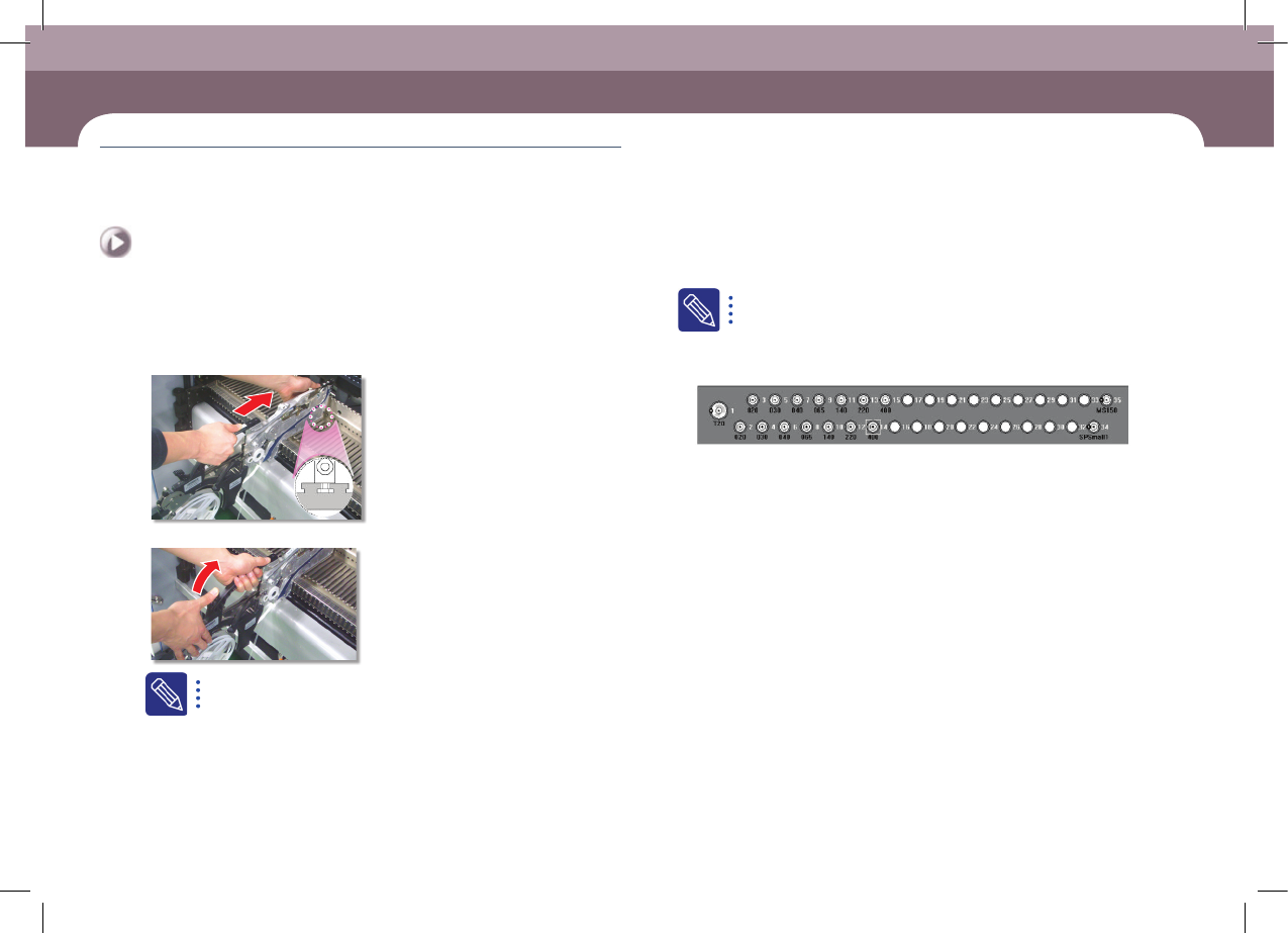
2. Check nozzle arrangement and install nozzles
ㆍ Check whether the nozzle arrangement corresponds to the actual arrangement
on the ANC by referring to the nozzle arrangement shape in the ANC dialog box.
ㆍ If the nozzle arrangement is different, arrange the nozzles according to the setup
for the PCB.
3. Check for parts expected to be exhausted
Check the details of parts expected to be exhausted soon, which were checked in
the previous 'Check related works' stage, and prepare an order list.
4. Order parts
Order the corresponding parts by submitting the prepared part order form to the
part supply department (material handling department). (At this time, obtain a
confirmation certificate for parts ordered and use it to check parts when delivered.)
For companies applying an IT system, their part supply department may prepare
parts in advance by receiving information on the remaining part count from the
machine's MMI.
5. Check the dump box
Check whether the dump box is installed properly.