00198536-02_AI_Mixed-Mode_TX2iV1_TX2V2_de_en.pdf - 第100页
3 Installation 3.3 Connecting the vacuum pump 100 Assembly Instructions / Montageanleitung SIPLACE TX2i V1 SIPLACE TX2 V2 Option Mixed-Mode 01/2019 Procedure Fig.36: Adapting the hose connections of the vacuum pump 1 Fa…
3 Installation
3.3 Connecting the vacuum pump
Assembly Instructions / Montageanleitung SIPLACE TX2i V1 SIPLACE TX2 V2 Option Mixed-Mode 01/2019 99
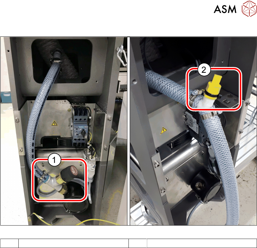
Overview of connections - mixed mode (after the conversion)
Fig.35: Connections in mixed mode
1 Vacuum control valve [03162136‑xx] 2 Grip cap [03210738‑xx]
3 Installation
3.3 Connecting the vacuum pump
100 Assembly Instructions / Montageanleitung SIPLACE TX2i V1 SIPLACE TX2 V2 Option Mixed-Mode 01/2019
Procedure
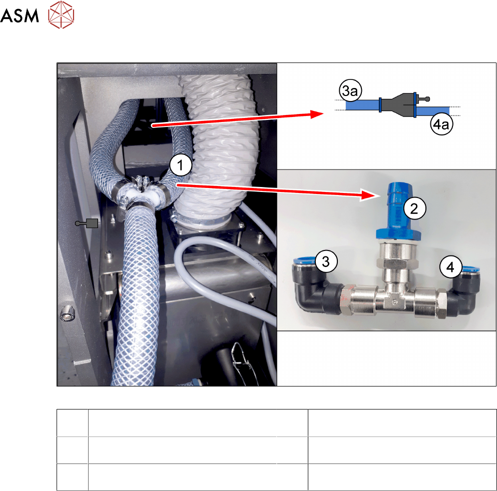
Fig.36: Adapting the hose connections of the vacuum pump
1 Fabric hose to the pneumatics block 2 Connection for the fabric hose to the
pneumatics block
3 Pneumatic hose PUN16 from the propor-
tional valve (compressed air)
4 Pneumatic hose PUN12, placement cir-
cuit to the pneumatics block
3a Pneumatics hose from the proportional
valve (compressed air)
4a Pneumatic hose to the pneumatics block
(for placement circuit)
► Pull the hose(1) off the Y piece and connect it to connection(2) of the "Upgrade kit 2 pneu-
matics" [03162637‑xx].
► Pull the two hoses (3a) and (4a) behind the vacuum pump out of the machine frame. The two
hoses are connected with a Y piece.
► Connect the hose (3a) to connection(3).
► Connect the hose (4a) to connection(4).
3 Installation
3.4 Converting the COT-i
Assembly Instructions / Montageanleitung SIPLACE TX2i V1 SIPLACE TX2 V2 Option Mixed-Mode 01/2019 101
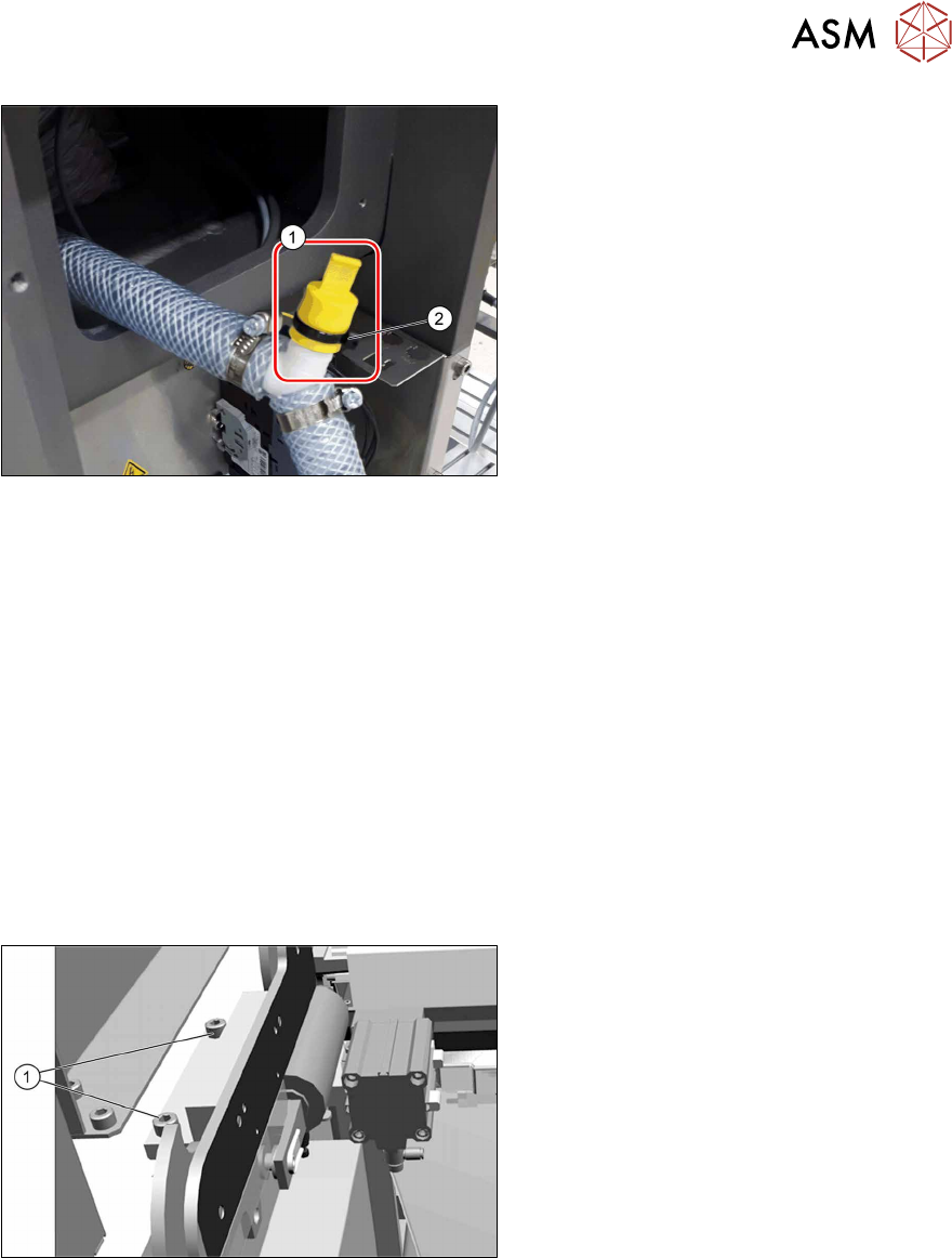
Fig.37: Grip cap
► Close the open connection at the Y
piece with the grip cap(1).
Secure the grip cap with a cable tie(2).
See also
2 3.2.2 "Creating access to the pneumatics block and modifying the hose connections" [}89]
3.4 Converting the COT-i
The nozzle changer and the nozzle station on the location side of the SIPLACE CPP head need to
be set deeper. This requires the conversion of the COT-i. If this is not performed, there could be a
collision with the nozzle shaft of the CPP nozzles and the SIPLACE C&P20x head!
For this, the holders on the left and right of the nozzle changer and the holder for the nozzle station
must be replaced. To do so, proceed as follows (SIPLACETXV1 used as example):
See also:
SIPLACE TX2i V1:
4.1.2.3 "Replacing the COT-i-i central unit and lifting mechanics" [}107]
SIPLACE TX2 V2:
4.1.3.3 "Replacing the COT‑i" [}122]
Fig.38: Lifting mechanism on the COT-i
► Remove the two screws(1) on the left
and right side of the lifting mechanism
for the COT-i.
This lifting mechanism can be com-
pletely removed, if necessary.