00198536-02_AI_Mixed-Mode_TX2iV1_TX2V2_de_en.pdf - 第102页
3 Installation 3.4 Converting the COT-i 102 Assembly Instructions / Montageanleitung SIPLACE TX2i V1 SIPLACE TX2 V2 Option Mixed-Mode 01/2019 Fig.39: Two screws (1) on the left side of the lifting mechanism for the COT-…
3 Installation
3.4 Converting the COT-i
Assembly Instructions / Montageanleitung SIPLACE TX2i V1 SIPLACE TX2 V2 Option Mixed-Mode 01/2019 101
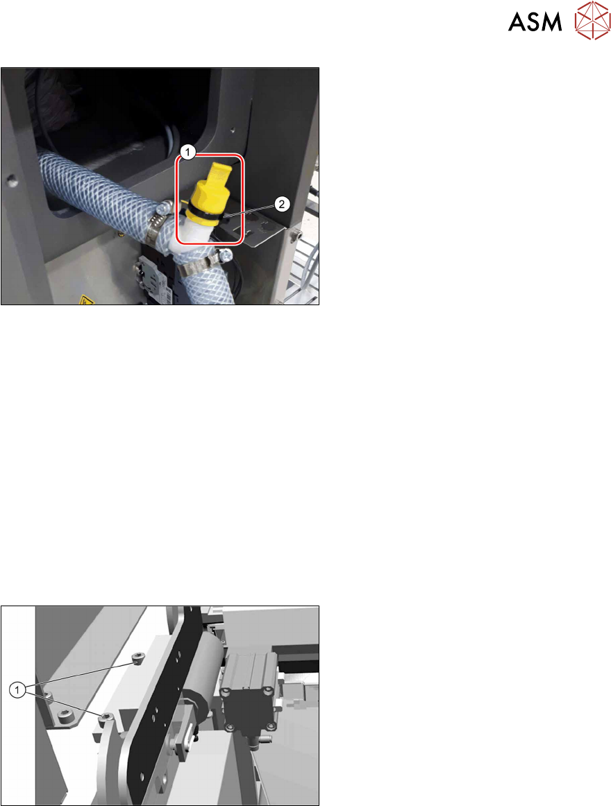
Fig.37: Grip cap
► Close the open connection at the Y
piece with the grip cap(1).
Secure the grip cap with a cable tie(2).
See also
2 3.2.2 "Creating access to the pneumatics block and modifying the hose connections" [}89]
3.4 Converting the COT-i
The nozzle changer and the nozzle station on the location side of the SIPLACE CPP head need to
be set deeper. This requires the conversion of the COT-i. If this is not performed, there could be a
collision with the nozzle shaft of the CPP nozzles and the SIPLACE C&P20x head!
For this, the holders on the left and right of the nozzle changer and the holder for the nozzle station
must be replaced. To do so, proceed as follows (SIPLACETXV1 used as example):
See also:
SIPLACE TX2i V1:
4.1.2.3 "Replacing the COT-i-i central unit and lifting mechanics" [}107]
SIPLACE TX2 V2:
4.1.3.3 "Replacing the COT‑i" [}122]
Fig.38: Lifting mechanism on the COT-i
► Remove the two screws(1) on the left
and right side of the lifting mechanism
for the COT-i.
This lifting mechanism can be com-
pletely removed, if necessary.
3 Installation
3.4 Converting the COT-i
102 Assembly Instructions / Montageanleitung SIPLACE TX2i V1 SIPLACE TX2 V2 Option Mixed-Mode 01/2019
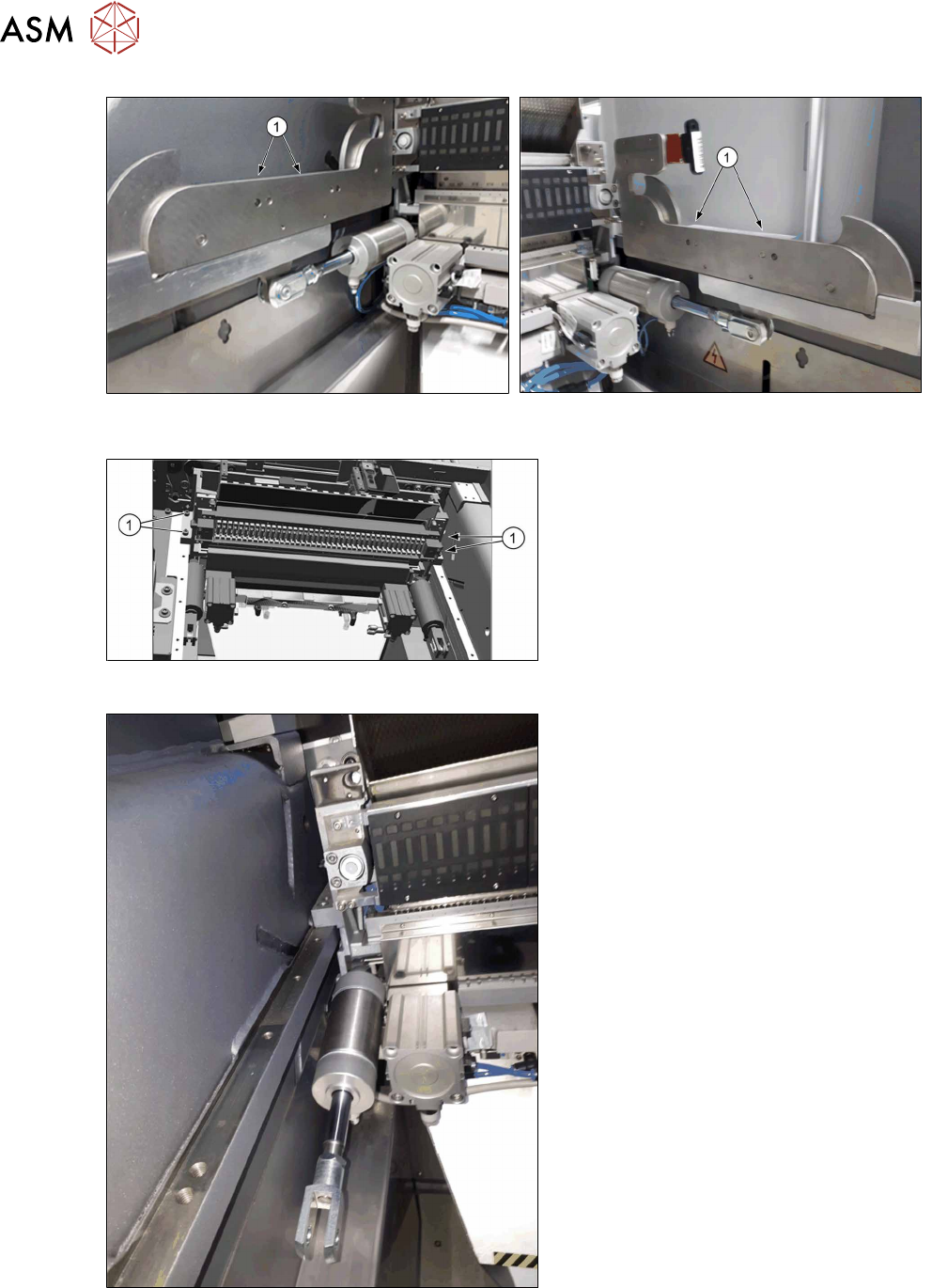
Fig.39: Two screws (1) on the left side of the lifting
mechanism for the COT-i
Fig.40: Two screws (1) on the right side of the lifting
mechanism for the COT-i
Fig.41: FCU central unit
► Remove the two screws on the left and
right of the FCU central unit (1).
Fig.42: Pulling the COT-i forwards
► Now pull the entire COT-i forwards, to
gain access to its bracket.
This bracket is screwed to the back of
the FCU central unit.
3 Installation
3.4 Converting the COT-i
Assembly Instructions / Montageanleitung SIPLACE TX2i V1 SIPLACE TX2 V2 Option Mixed-Mode 01/2019 103
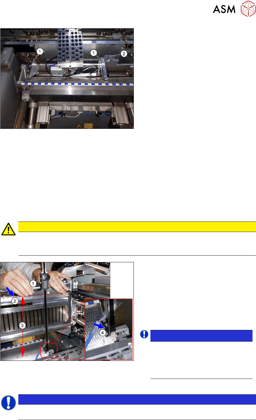
Fig.43: Retaining bracket
► Remove the nozzle changer and nozzle
station.
► Replace the two brackets(1) and the
nozzle station holder(2) with the same
parts.
► Pay attention to the reject bin sensor
and the running of the hose for the
nozzle station.
► Fit the COT-i.
Checking the installation height of the NC
Before you fit the NC and nozzle station, check the installation height.
For more information, see the following sections:
SIPLACE TX2i V1:
4.1.2.4 "Replacing the Nozzle Changer" [}112]
4.1.2.6 "Replacing the nozzle station" [}116]
SIPLACE TX2 V2:
4.1.3.4 "Replacing the Nozzle Changer" [}126]
4.1.3.5 "Replacing the nozzle station" [}129]
► Check the NC installation height as follows:
CAUTION
Deviating values
The values specified here deviate from the default values due to the mixed mode configura-
tion!
Fig.44: Checking the installation height
► Position the measuring scale(1) on the
top edge of the Xaxis upper linear
guide(2) and measure the distance to
the nozzle changer contact surface(4).
Correct installation height (3) of the NC in
mixed mode:
SIPLACE TX2i V1: 280.65 +/‑0.2mm
SIPLACE TX2 V2: 282.65 +/‑0.2mm
► If required, use shim plates.
NOTICE!
Alternatively, you can measure from
the top edge of the lower guide rail of
the gantry.
SIPLACE TX2i V1: 119.65 +/‑0.2 mm
SIPLACE TX2 V2: 121.65 +/‑0.2 mm
.
► Check the installation height of the nozzle station as follows:
NOTICE
In contrast to the nozzle changer, the installation height of the nozzle station is not
changed in the mixed mode option.