00198536-02_AI_Mixed-Mode_TX2iV1_TX2V2_de_en.pdf - 第89页
3 Installation 3.2 Adapting the hose connections at the pneumatics block Assembly Instructions / Montageanleitung SIPLACE TX2i V1 SIPLACE TX2 V2 Option Mixed-Mode 01/2019 89 3.2.2 Creating access to the pneumatics block …
3 Installation
3.2 Adapting the hose connections at the pneumatics block
88 Assembly Instructions / Montageanleitung SIPLACE TX2i V1 SIPLACE TX2 V2 Option Mixed-Mode 01/2019
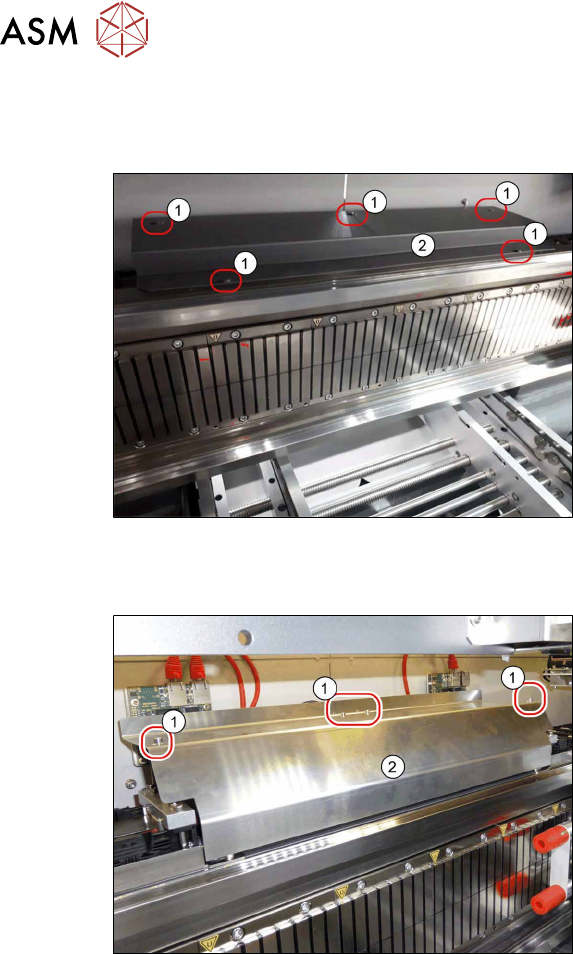
3.2.1 Removing the cover of the trailing interface
SIPLACE TX V1:
Fig.13: Cover over the trailing interface 1 and2
► Remove the five screws(1) of the
cover(2) over trailing interface1 and2.
► Lift off the cover.
SIPLACE TX V2:
Fig.14: Cover
► Loosen the four fastening screws(1)
(Allen key2.5).
► Pull the cover (2) slightly forwards and
then take it up and off.
3 Installation
3.2 Adapting the hose connections at the pneumatics block
Assembly Instructions / Montageanleitung SIPLACE TX2i V1 SIPLACE TX2 V2 Option Mixed-Mode 01/2019 89
3.2.2 Creating access to the pneumatics block and modifying the hose
connections
NOTICE
The following description shows the conversion for configuration of gantry1 with C&P20x
head (vacuum pump) and gantry2 with CPP head.
The procedure for configuration of gantry2 with C&P20x head (vacuum pump) and gantry1
with CPP head is the same.
NOTICE
Do not loosen the screws of both trailing interfaces at the same time.
► Begin with the trailing interface for the gantry without vacuum hoses (gantry with
CPP).
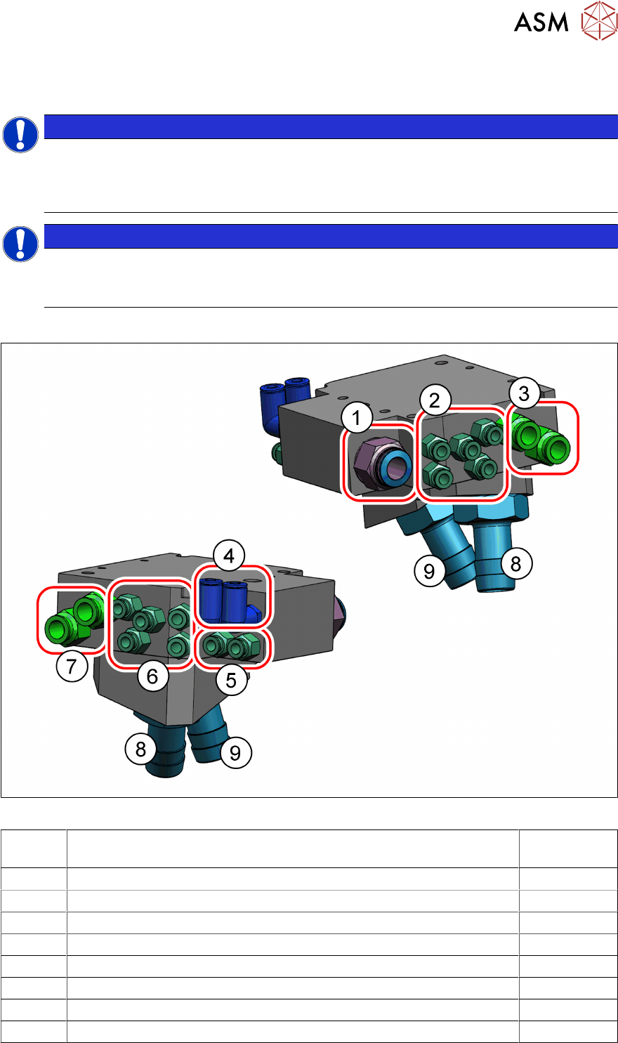
Overview - pneumatics block
Fig.15: Connections on the pneumatics block (using a SIPLACETXV2 as example)
1 Pneumatic hose PUN12 from proportional valve (compressed air place-
ment circuit inlet)
2 5x connections for the 7-fold hose in the trailing cable Gantry 1
3 2x vacuum hoses (Camozzi) Gantry 1
4 2x connections 7-fold hose (placement circuit outlet) Gantry 1
5 2x connections 7-fold hose (placement circuit outlet) Gantry 2
6 5x connections for 7-fold hose Gantry 2
7 2x vacuum hoses (Camozzi) Gantry 2
8 Fabric hose vacuum
9 Fabric hose compressed air or vacuum
3 Installation
3.2 Adapting the hose connections at the pneumatics block
90 Assembly Instructions / Montageanleitung SIPLACE TX2i V1 SIPLACE TX2 V2 Option Mixed-Mode 01/2019
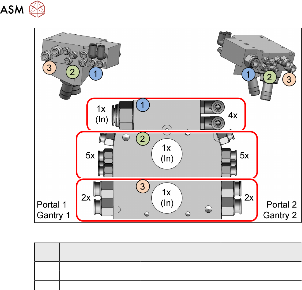
Fig.16: Overview of the three chambers in the pneumatics block with the according connections (Using a
SIPLACETXV2 as example)
Item in
figure
Initial situation With mixed mode
Without vacuum pump With vacuum pump
1 Compressed Air Compressed Air Compressed Air
2 Compressed Air Vacuum Compressed Air
3 Not connected Vacuum Vacuum