00198536-02_AI_Mixed-Mode_TX2iV1_TX2V2_de_en.pdf - 第104页
3 Installation 3.5 Performing final work 104 Assembly Instructions / Montageanleitung SIPLACE TX2i V1 SIPLACE TX2 V2 Option Mixed-Mode 01/2019 Fig.45: Setting the height of the nozzle station (taking the standard nozzle…
3 Installation
3.4 Converting the COT-i
Assembly Instructions / Montageanleitung SIPLACE TX2i V1 SIPLACE TX2 V2 Option Mixed-Mode 01/2019 103
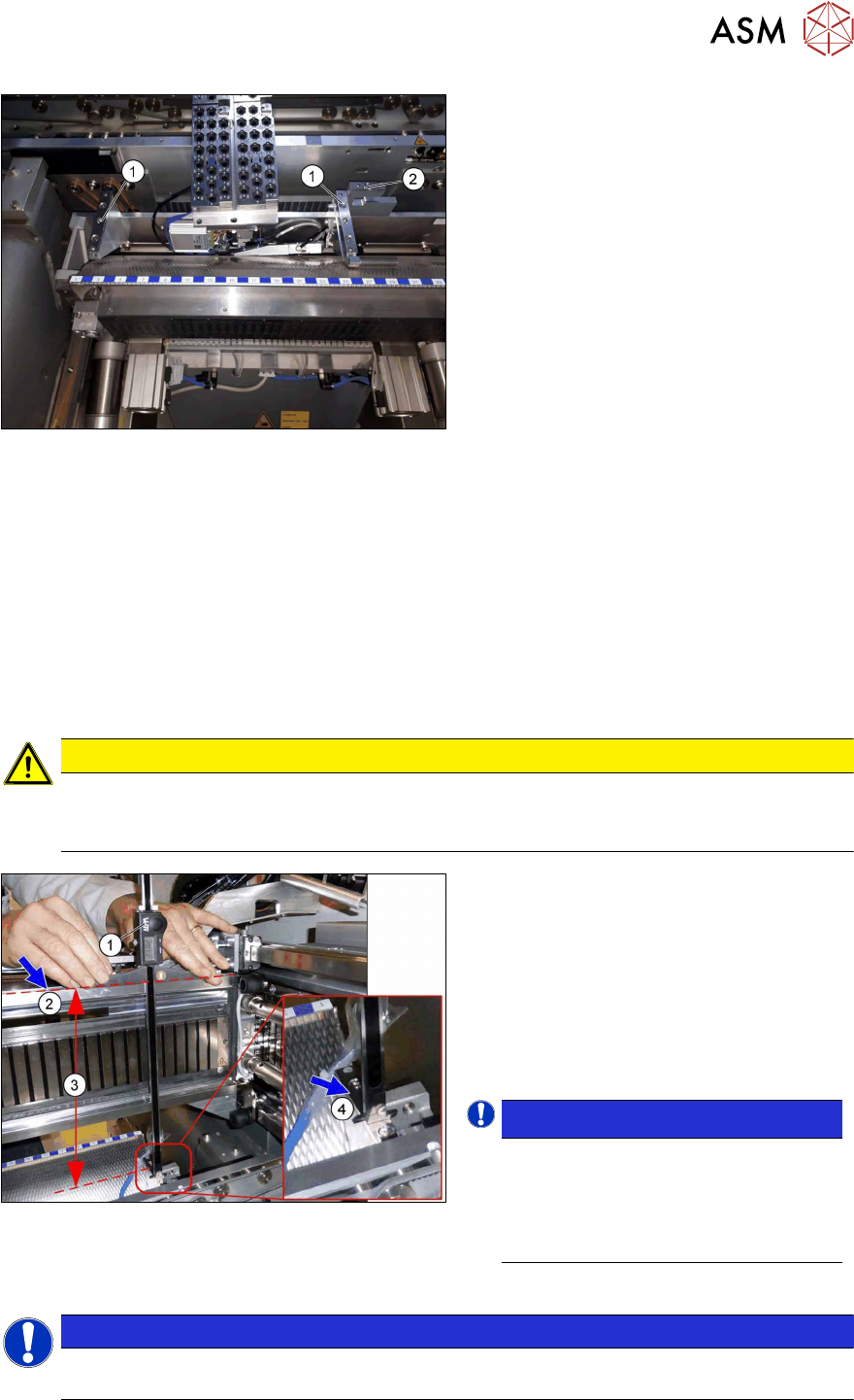
Fig.43: Retaining bracket
► Remove the nozzle changer and nozzle
station.
► Replace the two brackets(1) and the
nozzle station holder(2) with the same
parts.
► Pay attention to the reject bin sensor
and the running of the hose for the
nozzle station.
► Fit the COT-i.
Checking the installation height of the NC
Before you fit the NC and nozzle station, check the installation height.
For more information, see the following sections:
SIPLACE TX2i V1:
4.1.2.4 "Replacing the Nozzle Changer" [}112]
4.1.2.6 "Replacing the nozzle station" [}116]
SIPLACE TX2 V2:
4.1.3.4 "Replacing the Nozzle Changer" [}126]
4.1.3.5 "Replacing the nozzle station" [}129]
► Check the NC installation height as follows:
CAUTION
Deviating values
The values specified here deviate from the default values due to the mixed mode configura-
tion!
Fig.44: Checking the installation height
► Position the measuring scale(1) on the
top edge of the Xaxis upper linear
guide(2) and measure the distance to
the nozzle changer contact surface(4).
Correct installation height (3) of the NC in
mixed mode:
SIPLACE TX2i V1: 280.65 +/‑0.2mm
SIPLACE TX2 V2: 282.65 +/‑0.2mm
► If required, use shim plates.
NOTICE!
Alternatively, you can measure from
the top edge of the lower guide rail of
the gantry.
SIPLACE TX2i V1: 119.65 +/‑0.2 mm
SIPLACE TX2 V2: 121.65 +/‑0.2 mm
.
► Check the installation height of the nozzle station as follows:
NOTICE
In contrast to the nozzle changer, the installation height of the nozzle station is not
changed in the mixed mode option.
3 Installation
3.5 Performing final work
104 Assembly Instructions / Montageanleitung SIPLACE TX2i V1 SIPLACE TX2 V2 Option Mixed-Mode 01/2019
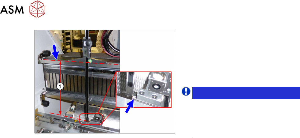
Fig.45: Setting the height of the nozzle station
(taking the standard nozzle station as example)
► Measure the distance(1) between the
contact surface of the nozzle station
and the top edge of the upper guide rail
of the gantry.
SIPLACE TX2i V1: 266.0+0.1/‑0.3mm
SIPLACE TX2 V2: 268.0+0.1/‑0.3mm
► If required, use shim plates.
NOTICE!
Alternatively, you can measure from
the top edge of the lower guide rail of
the gantry.
SIPLACE TX2i V1: 105.0+0.1/‑0.3mm
SIPLACE TX2 V2: 107.0+0.1/‑0.3mm
.
► Now fit the nozzle changer and nozzle station.
3.5 Performing final work
► Finish all mechanical tasks (fitting covers etc.) and start the machine.
► Acknowledge the warning which appears when you first start the station SW.
► Check the autoconfig., to make sure that the vacuum pump option has been set.
► Check the head configuration in the autoconfig.
4 Appendix
4.1 Excerpts from the Service Manual
Assembly Instructions / Montageanleitung SIPLACE TX2i V1 SIPLACE TX2 V2 Option Mixed-Mode 01/2019 105
4 Appendix
4.1 Excerpts from the Service Manual
The following chapters are excerpts from the service manual for your machine. If required, further
information is provided there.
●
Service manual SIPLACE TX-Series V1 [DE:00198149‑xx] [EN:00198150‑xx]
●
Service manual SIPLACE TX-Series V2 [DE:00198538‑xx] [EN:00198539‑xx]
4.1.1 Replacing the trailing interface
4.1.2 SIPLACE TX V1
4.1.2.1 Replacing the Trailing Cable Interface
Parts, equipment and tools
●
Trailing interface 1 [03115810-xx]
●
Trailing interface 2 [03115814-xx]
NOTICE
SIPLACE TX micron machines
The functionality level of the trailing interface must be at least -02 for SIPLACE TX micron
machines.
Overview
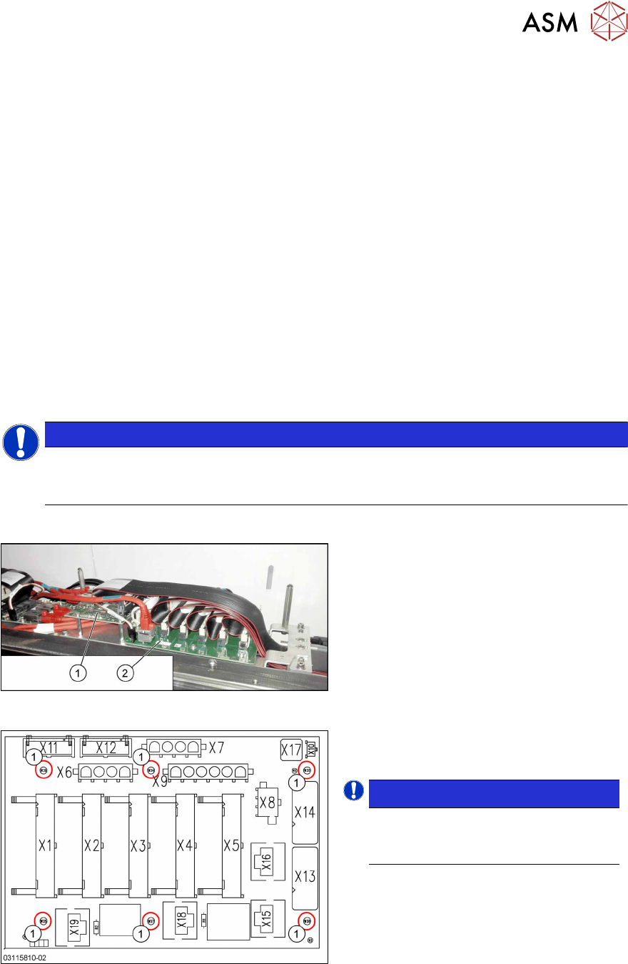
Fig.46: Vision base interface and trailing cable interface
1. Vision base interface (VBI)
2. Trailing cable interface
Fig.47: Trailing interface
Trailing interface [03115810-xx]
1. Six fastening screws
NOTICE!
Inverse layout
The layout of the two trailing interfaces
is the same, but inversely.
.