00198536-02_AI_Mixed-Mode_TX2iV1_TX2V2_de_en.pdf - 第109页
4 Appendix 4.1 Excerpts from the Service Manual Assembly Instructions / Montageanleitung SIPLACE TX2i V1 SIPLACE TX2 V2 Option Mixed-Mode 01/2019 109 Fig.54: Removing the lifting mechanics ► Dismantle the lifting mechan…
4 Appendix
4.1 Excerpts from the Service Manual
108 Assembly Instructions / Montageanleitung SIPLACE TX2i V1 SIPLACE TX2 V2 Option Mixed-Mode 01/2019
Parts, equipment and tools
●
Suitable lifting device (e.g. hand-operated crane)
●
Detailed circuit diagrams folder for SIPLACE TX V1-Series (up to no. 499) [DE+EN: 00197933-xx]
●
Detailed circuit diagrams folder for SIPLACE TX V1-Series (from no. 500) [DE+EN:00198274-xx]
●
Detailed circuit diagrams SIPLACE TX V2-Series [DE+EN: 00198460-xx]
Fig.52: COT‑i central unit assy [03117339‑xx]
(complete with FCU and tape cutter)
●
Select the required parts (also see
below):
– Lifting mechanics left assy
[03126040‑xx]
– Lifting mechanics right assy
[03126039‑xx]
– COT‑i central unit assy
[03117339‑xx]
(complete with FCU and tape cutter)
Removal of left and right lifting mechanics
NOTICE
Shown by example
The following procedure is shown by example of the left lifting mechanics. The procedure
for the right lifting mechanics the same. Relevant differences will be mentioned.
► Switch off the machine, disconnect it from the power supply and secure it to prevent
unauthorized reactivation.
1.2 "Preparatory work..." [}77]
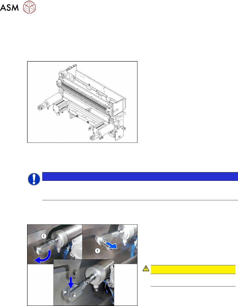
Fig.53: Locking flap
The safety bolt(1) fixes the connection
between the pneumatic cylinder and the lift-
ing mechanics.
► Flip the safety catch down.
► Remove the safety bolt, to access the
connection.
CAUTION!
Pay attention to the position and
number of washers used.
.
4 Appendix
4.1 Excerpts from the Service Manual
Assembly Instructions / Montageanleitung SIPLACE TX2i V1 SIPLACE TX2 V2 Option Mixed-Mode 01/2019 109
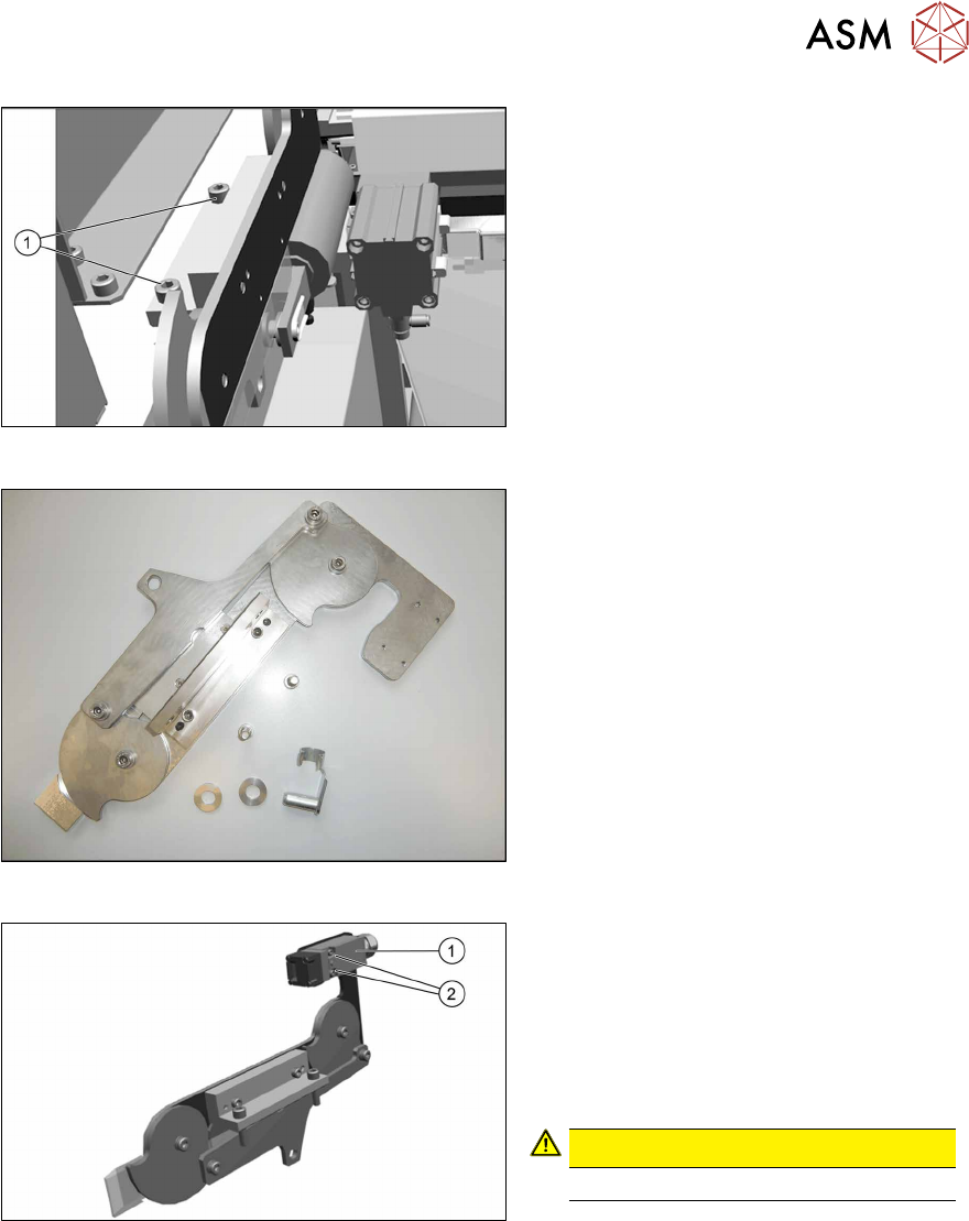
Fig.54: Removing the lifting mechanics
► Dismantle the lifting mechanics by re-
moving the screws(1).
Fig.55: Lifting mechanics parts
► Take out the "left lifting mechanics
assembly" [03126040‑xx].
Fig.56: Safety switch
► Repeat for the right lifting mechanics if
necessary.
The procedure for the right lifting mechanics
is the same, the only difference being that
the safety switch(1) must be removed.
► Remove the two fastening screws(2) of
the safety switch.
CAUTION!
Do not loose the sleeves.
.
4 Appendix
4.1 Excerpts from the Service Manual
110 Assembly Instructions / Montageanleitung SIPLACE TX2i V1 SIPLACE TX2 V2 Option Mixed-Mode 01/2019
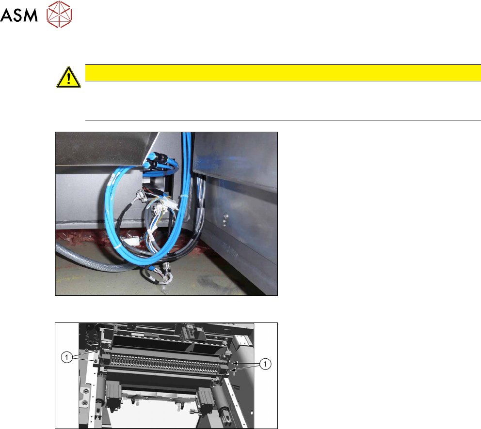
Removing the COT-i central unit
CAUTION
Heavy machine part!
The COT-i central unit is heavy. To lift it out, you will need to use the fit-up aid and a suit-
able lifting device (hand-operated crane etc.).
Fig.57: Central unit connections
► Disconnect all connections to the cent-
ral unit.
Fig.58: Central unit fastening screws
► Remove the four fastening screws(1).
► Remove the central unit out of the
machine.