00198536-02_AI_Mixed-Mode_TX2iV1_TX2V2_de_en.pdf - 第112页
4 Appendix 4.1 Excerpts from the Service Manual 112 Assembly Instructions / Montageanleitung SIPLACE TX2i V1 SIPLACE TX2 V2 Option Mixed-Mode 01/2019 Installing the lifting mechanics Fig.61: Installing the lifting mecha…
4 Appendix
4.1 Excerpts from the Service Manual
Assembly Instructions / Montageanleitung SIPLACE TX2i V1 SIPLACE TX2 V2 Option Mixed-Mode 01/2019 111
Installation of central unit
Follow the removal instructions in reverse order for installation.
► If necessary move the cutter and the FCU from the old to the new COT-i.
► Lift the COT-i out of the machine. Use a suitable lifting device.
► Reconnect all cables and hoses. Observe the detailed circuit diagram, if needed.
► Move the COT-i into its final position on the machine frame.
Take care not to damage the cables and hoses.
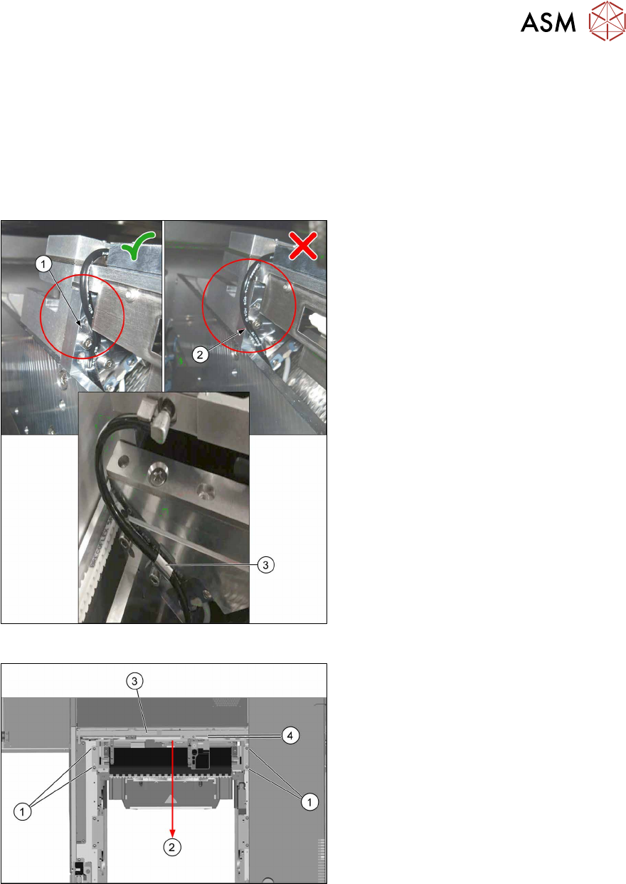
Fig.59: Hoses for the nozzle station air supply
► Check the hoses for the nozzle station
air supply:
1. Hose 1 is recommended. The hose is
running behind the screw head, so the
lining of the hose will not touch the con-
veyor belt.
2. Hose 2 is not recommended, as it may
touch the conveyor belt and will be cut
over time.
3. Use the hose clamp.
Fig.60: Fixing the central unit (shown from above)
► Put in the four screws(1) in position
and loosely tighten them.
► Move the central unit to the outer side
of the machine(2) to ensure a max-
imum distance(4) to the conveyor
side(3).
► The further installation of the central unit is performed by following the above instructions in
the reverse order.
4 Appendix
4.1 Excerpts from the Service Manual
112 Assembly Instructions / Montageanleitung SIPLACE TX2i V1 SIPLACE TX2 V2 Option Mixed-Mode 01/2019
Installing the lifting mechanics
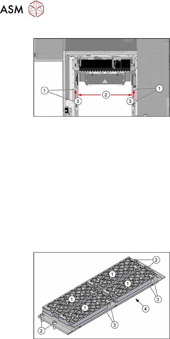
Fig.61: Installing the lifting mechanics
► Mount the interlock safety switch to the
right lifting mechanics.
► Place both lifting mechanics (left and
right) in position and fix them with two
screws(1) each.
► Move both lifting mechanics to the
outer position(2) push them towards
the inner side(3) and tighten the
screws(1).
► Reconnect the lifting mechanics to the pneumatic cylinders.
► Insert the locking flap bolt and place the washers in the correct position! Start at the inner side
at the COT-i.
► Close the locking flap to fix the connection between the lifting mechanics and pneumatic cylin-
der.
► Perform necessary calibrations for the location.
4.1.2.4 Replacing the Nozzle Changer
Parts, Equipment and Tools
●
NC basic structure CPx/all assembly short [03103649-xx]
●
If required, NC adjusting plates [03021079-xx]
●
Depth measuring gauge (300mm) [03079617-xx]
Overview
Fig.62: Nozzle changer with four 4xxx magazines
1. Four nozzle magazines
2. Four fastening screws
3. Four levers for removal of nozzle
magazines
4. Cover on the underside
The electronic and pneumatic compon-
ents are under the cover.
Removal
► Switch off the machine, disconnect it from the power supply and secure it to prevent
unauthorized reactivation.
1.2 "Preparatory work..." [}77]
► Remove all magazines.
► Remove the four fastening screws.
► Unplug the nozzles changer from all electrical and pneumatic connections.
► Take care not to lose the support plates.
► Carefully lift the nozzle changer out of the machine.
4 Appendix
4.1 Excerpts from the Service Manual
Assembly Instructions / Montageanleitung SIPLACE TX2i V1 SIPLACE TX2 V2 Option Mixed-Mode 01/2019 113
Installation
► Follow the removal instructions in reverse order for installation. Also observe the following
instructions:
CAUTION
Installation instructions
► Set the switch on the nozzle changer to 2-3 (valid for all SIPLACE TX machines).
► Check the mechanical installation height of the nozzle changer (see 4.1.2.4.1 "Setting
the Nozzle Changer Height" [}113]).
4.1.2.5 "Jumpers on the Nozzle Changer" [}115]
Setting the Nozzle Changer Height
Parts, equipment and tools
●
Measuring scale
●
NC shim plate (0.3mm) [03021079-xx]
Overview
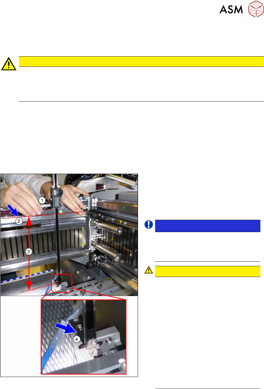
Fig.63: Overview of measurement procedure
1. Measuring scale
2. Top edge of the X axis upper linear
guide
3. Values to be set (277 +/- 0.2 mm)
4. Nozzle changer contact surface
NOTICE!
Alternatively, you can measure from
the top edge of the lower guide rail of
the gantry. In this case the distance is
116.0+/‑0.2mm.
.
CAUTION!
Only with mixed mode option
If applicable, observe the deviating
measurements for the mixed mode op-
tion:
Installation height of NC:
280.65 +/ 0.2 mm
Measured from the upper edge of the
top linear guide
OR
119.65 +/ 0.2 mm
Measured from the upper edge of the
bottom linear guide
See also the assembly instruction
manual "Option Mixed Mode –
SIPLACE TX2i" [00198536‑xx]
.