EUS0153210_YFact_Standard_E.pdf - 第231页
5-4 5 Rank T able Editor 2 Pattern name group Group the board data pattern names. Combine the pattern names for the board data into a single group. As an example, we will explain the case in which there are three pattern…
5-3
5
Rank Table Editor
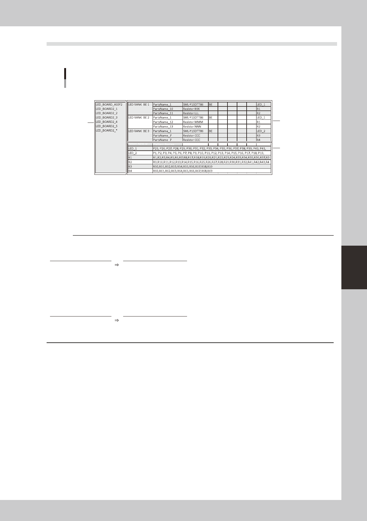
1.2 Specifying the Part Characteristics (BIN)
To edit a BIN table, use BIN Table Editor. Make settings in the order of items marked 1 through 3 in the
illustration.
1
3
2
Specifying the part characteristics (BIN)
64758-T2-00
1 Production model / Board name
Specify the production model (or board name) that uses this BIN table. Note that what you specify will depend on the
mode.
Playmode : Enterthe"productionmodel(ASSY)"thatisspecifiedintheprogramlist.
Machinemode: Entertheboarddataname.
Reference
You can use wildcards when specifying the production model or board name.
Example) Specifying a different board name for each machine in Play mode
Target board Wildcard expression
ProductA_Ver_201408
ProductA_Ver_*
ProductA_Ver_201409
ProductA_Ver_201410
ProductA_Ver_201411
ProductA_Ver_201412
Example) Specifying a different board name for each machine in Machine mode
Target board Wildcard expression
ProductA_YS12
ProductA_*
ProductA_YS24
ProductA_YS24X
5-4
5
Rank Table Editor
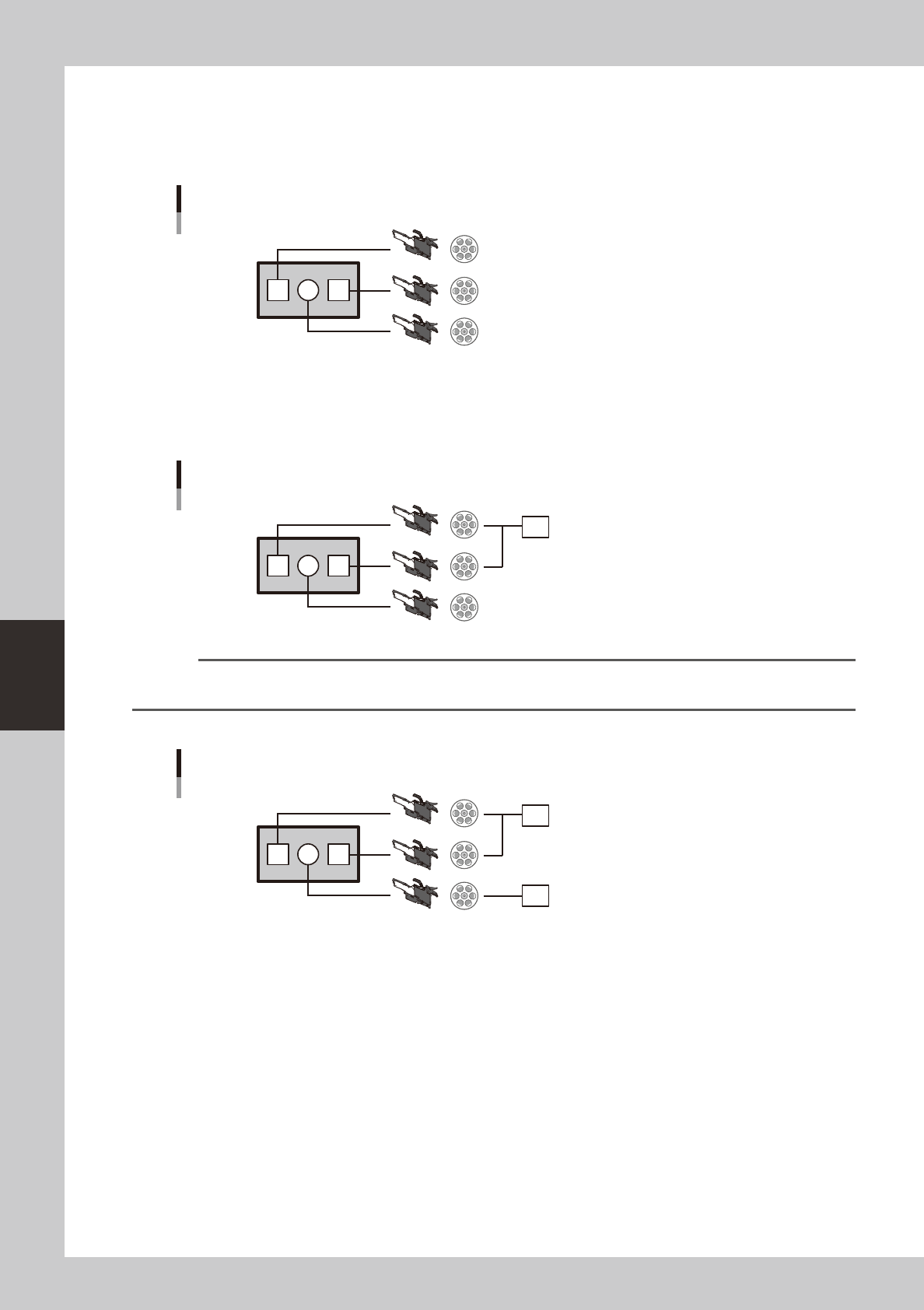
2 Pattern name group
Group the board data pattern names. Combine the pattern names for the board data into a single group. As an example,
we will explain the case in which there are three patterns P1, P2, and P3, where parts with characteristic A are installed
for P1 and P3, and parts with characteristic B are installed for P2.
Production example
P1 P2 P3
64759-T2-00
Make a group of P1 and P3. You are free to specify a name for the pattern name group. In this example, we call it PG1
(an abbreviation of Pattern Group 1).
This pattern name group is the unit by which part characteristics are assigned. Thus, since P1 and P3 belong to the same
pattern group (PG1), the same characteristics specifications are applied.
Create the pattern name group "PG1"
P1 P2 P3
PG1
647560-T2-00
Reference
In the illustration, P1 and P3 are separate feeders, but the case is the same even if the parts are supplied from a single
feeder.
Next, assign the pattern name group "PG2" to P2.
Create the pattern name group "PG2"
P1 P2 P3
PG1
PG2
64761-T2-00
5-5
5
Rank Table Editor
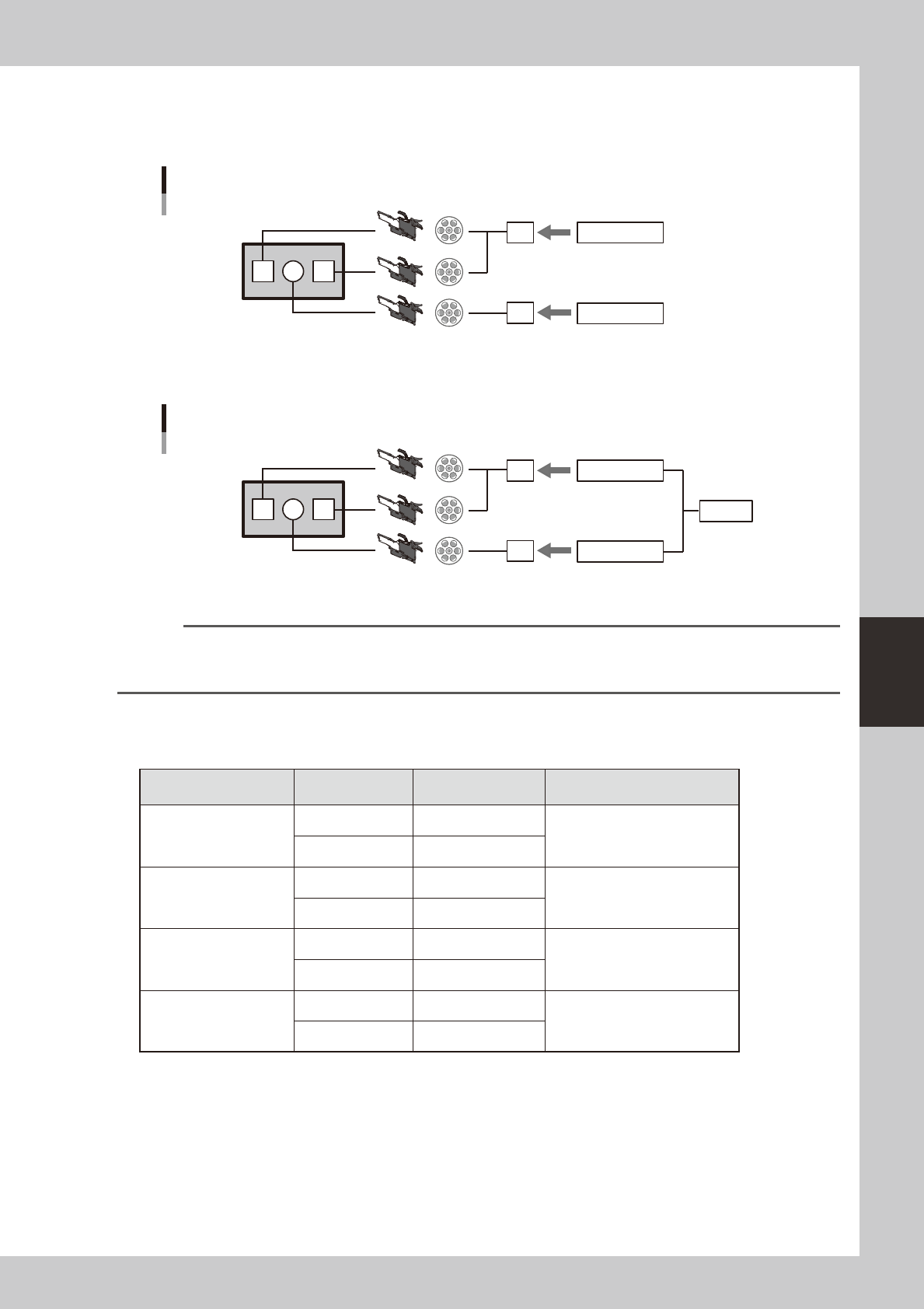
3 Combination
Next, assign part characteristics to each pattern name group. Assign characteristic A to PG1 which you created earlier in
"2 Pattern name group," and assign characteristic B to PG2.
Assign part characteristics
P1 P2 P3
PG1
PG2
Characteristic A
Characteristic B
64762-T2-00
If there is a correlation between PG1 and PG2, define this correlation as a "combination." You are free to specify a name.
In this example, we call the combination Combi_AB (Combination A B).
Define a combination
P1 P2 P3
PG1
PG2
CombiAB
Characteristic A
Characteristic B
64763-T2-00
Subsequently we use this combination to specify characteristics.
Reference
In the example above, specifying Combi_AB simultaneously specifies characteristic A and characteristic B. If you want
to specify the characteristic individually, define them separately as PG1_A and PG2_B so that they can be specified
individually.
Specify the patterns that you will need for production. You will select a pattern at production time. These are referred to
as the BIN tables.
Example) Simplified illustration of specifying characteristics *Part names etc. are omitted
Combination
Pattern name
group
Characteristic Note
Combi_AB
PG1 A
PG2 B
Combi_BA
PG1 B
Opposite pattern from Combi_AB
PG2 A
Combi_AA
PG1 A
Specify all A
PG2 A
Combi_BB
PG1 B
Specify all B
PG2 B