EUS0153210_YFact_Standard_E.pdf - 第64页
2-30 2 Board Explorer 4.2.3 About “F AST” (YVi Series) FAST conversion is another function to convert into the VADMIC steps instead of skip steps. Using FAST conversion the converted inspection data has a default VADMIC …
2-29
2
Board Explorer
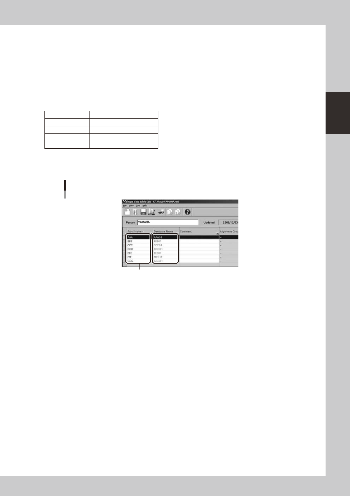
4.2.2 Type compatibility table
WhenconvertingboarddataofamountertotheInspectionprogram,librarypartnameofinspectorcanbe
added to the inspection data of part placement layout.
Withthisfunction,almostalltheinspectiondatawillbecompletedbyimportingtheconvertedInspection
program with the inspector unit or YViOS/YSiOS and then opening library with full distribution. (Some data
adjustment will be necessary.)
To use this function, it is necessary to create a correspondence table between parts name of the mounter and
library parts name of the inspector. If the correspondence table contains no data for a part, library part name
will be output as empty.
Mounter part name Library part name of inspector
AAA AAA01
BBB BBB01
CCC CCC01
: :
Typecorrespondencetablecanbecreatedwithtypecorrespondencetableeditor.Refertothemanualofthe
type correspondence table editor for instructions on how to use the tool.
Creation of type correspondence table
Input library part name for
the inspector.
Input part name for the mounter.
642C1-S0-00
2-30
2
Board Explorer
4.2.3 About “FAST” (YVi Series)
FAST conversion is another function to convert into the VADMIC steps instead of skip steps.
Using FAST conversion the converted inspection data has a default VADMIC parameter, so, only by registering
the good board images, it is possible to start simple inspection without library data.
n
NOTE
To use the FAST conversion, please set "ON" at the [FAST] setting beforehand as described in "4.2.4 How to set up"
below. Procedure of FAST conversion is the same as the usual conversion which is described in "4.2.1 Conversion of
Inspection program" above.
FAST conversion
642G0-S0-00
In the FAST conversion, multiple inspection steps are set for each mount points corresponding with the parts
alignment type of the mounter board data.
Each step size is also set depending on the parts size and parts shape, and suitable default parameters are set
foreachinspectiontarget(partsbody,solderandpartsleads).So,aftertheinspectormachineortheYVi-OS
imported the inspector data, it is possible to start inspection , without library data, only by the registering the
good board image.
2-31
2
Board Explorer
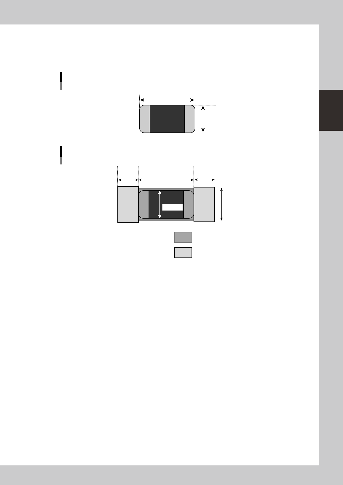
“What-liketheinspectionstepsareconvertedbyeachalignmenttype”isdescribedasbelow.
●
Chip Parts
Whenaboarddataofmounterincludeschippartsasbelow,andexecutesconversion,foreachmountpositionofthe
parts, this conversion set 1 step for parts body inspection and 2 steps for solder inspection.
Chip Parts
X (mm)
Y (mm)
63200-S0-00
Parts body inspection step
Solder inspection step
Y x1.1
X/3 X/3X
Y + 0.2mm
VADMIC inspection data of chip parts
63205-S0-00
But when the parts size is over 10mm, the Y size of parts body inspection step is set to Y size +1.0mm.
Each steps size is set as above picture.