00195166-0402_SM_D4_EN.pdf - 第128页
Service Work Modular Conveyor Replacing the Co mplete Lifting Tab le Cylinder [00358703] 128 Serv ice Manual SIPLACE D4 4.4.9 Replacing the Complete Li f ting T able Cylin der [00358703] Overview Removal DANGER: Press th…
Service Work
Replacing the Lifting Table Fork Light Barrier [00363079] Modular Conveyor
Service Manual SIPLACE D4
127
4.4.8 Replacing the Lifting Table Fork Light Barrier [00363079]
Parts
Light barrier for track A – dual conveyor [00363079-xx]
Light barrier for track B – dual conveyor [00363080-xx]
Light barrier for track A – single conveyor [00363111-xx]
Light barrier for track B – single conveyor [00363113-xx]
Removal/Installation
Legend
1. Connection cable for the conversion board of
the lifting table
2. 2 x fork light barrier (position measuring
system, tracks A + B)
3. Conversion board of the lifting table (under the
cover)
X Move the PCB conveyor to the position which
gives you best access to the lifting table.
X Move the Y gantries into the area outside the
PCB conveyor.
X Switch off the machine and secure it to prevent
unauthorized reactivation.
X Loosen the screw fastening the lifting table
plate and remove the lifting table plate from the
lifting table unit.
X Loosen the two screws (2) fastening the fork
light barrier.
X Remove the cover from the conversion board
of the lifting table (3).
X Unplug the lifting table conversion board.
X Fit the new fork light barrier and reconnect to
the electrical system.
1
3
2
Service Work
Modular Conveyor Replacing the Complete Lifting Table Cylinder [00358703]
128 Service Manual SIPLACE D4
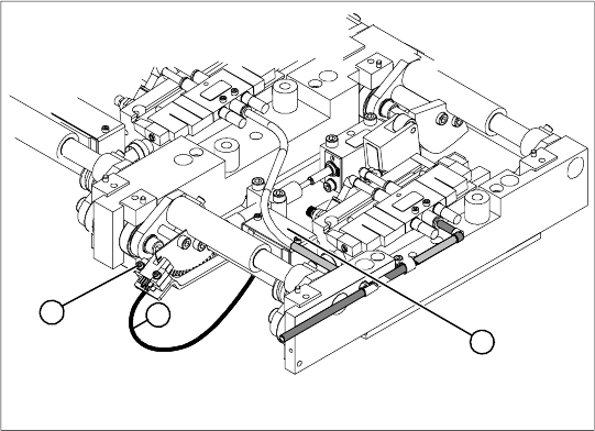
4.4.9 Replacing the Complete Lifting Table Cylinder [00358703]
Overview
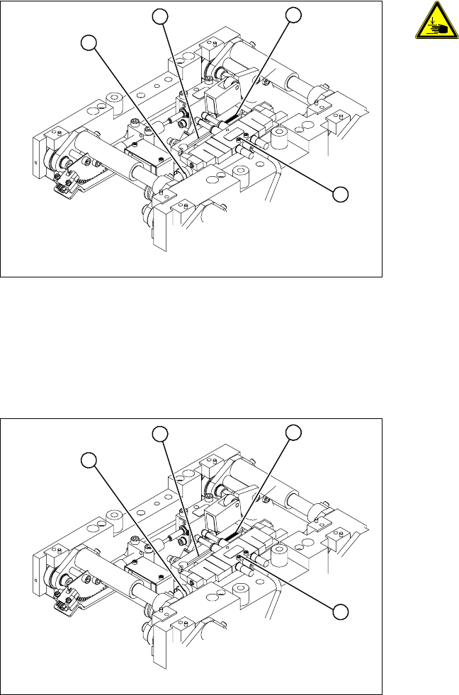
Removal
DANGER: Press the EMERGENCY
STOP!
Before performing adjustment work
you must ensure that the lifting table
has been secured against movement.
Legend
1. End position proximity switch
2. Lifting table cylinder
3. Piston rod with locknut
4. Solenoid valve
X Move the PCB conveyor to the position which
gives you best access to the lifting table.
X Move the Y gantries into the area outside the
PCB conveyor.
X Switch off the machine and secure it to prevent
unauthorized reactivation.
X Switch off the compressed air supply.
4
1
3
2
X Loosen the screw fastening the lifting table
plate and remove the lifting table plate from the
lifting table unit.
X Loosen the fastening screws for the solenoid
valve (4) and remove it from the lifting table
cylinder.
X Loosen the grub screw at the end position
proximity switch (1) and push the end position
proximity switch out of the lifting table cylinder
guide rail (2).
X Loosen the locknut on the piston rod (3) and
twist the piston rod out until it releases itself
from the actuator.
X Loosen and remove the two screws fastening
the lifting table cylinder (2).
4
1
3
2
Service Work
Replacing the Lifting Table Stabilizer (Stabilizer Unit) [00358684-xx] Mod ular Conveyor
Service Manual SIPLACE D4
129
Installation
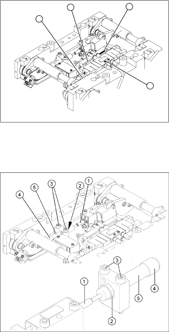
4.4.10 Replacing the Lifting Table Stabilizer (Stabilizer Unit) [00358684-xx]
Overview
Tools and equipment required
Torque wrench with plug-in ratchet [00386175-xx]
Plug-in wrench 16 mm [00386177-xx]
X Insert and fasten the new lifting table cylinder
(2) and install the piston rod (3).
X Move the lifting table by hand to its end
position.
X Switch the machine on.
X Push the end position proximity switch (1) into
the guide rail until the LED lights up.
X Fix this position with the grub screw.
X Install the solenoid valve (4) and the lifting
table plate.
X Check the speed of the lifting table and correct
where necessary.
4
1
3
2
Legend
1. Actuator
2. Locknut
3. Fastening screws
4. Handle
5. Stabilizer [00358684-xx]
The stabilizer enables the lifting table to be moved
gently upwards. It prevents the PCBs from being
clamped in with too much impact.
The stabilizer consists of the shock absorber
[00367737-xx] and the damping block [00367782-
xx].