00195166-0402_SM_D4_EN.pdf - 第222页
Settings C&P12 Boards at C&P12 222 Serv ice Manual SIPLACE D4 6.3.2 Boards at C&P12 All the settings described in this chapter ar e head-specific and apply here for the C&P12. 6.3.2.1 8-fold DIP Switch of…
Settings
Calibrating the C&P Head and Cameras C&P12
Service Manual SIPLACE D4
221
6.3 C&P12
6.3.1 Calibrating the C&P Head and Cameras
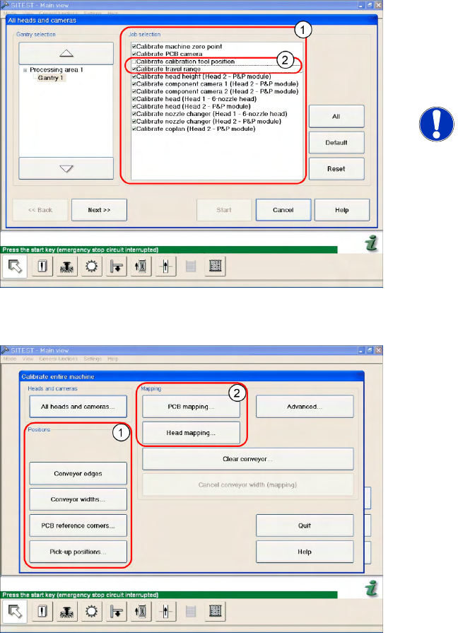
Automatic calibration of all heads and cameras
6-8: The menu may vary, according to the machine type and configuration.
X In the SITEST menu, select
Calibrate Entire
Machine
-->
All Heads and Cameras
to open
the adjacent menu.
X In
Job Selection
(1) , select the components
to be calibrated.
NOTE:
These two entries (2) are optional.
X To continue calibration with manual handling,
select the four consecutive menus in Section
Positions
(1) and the two menu items in the
Section
Mapping
(2).

Settings
C&P12 Boards at C&P12
222 Service Manual SIPLACE D4
6.3.2 Boards at C&P12
All the settings described in this chapter are head-specific and apply here for the C&P12.
6.3.2.1 8-fold DIP Switch of the gantry head distributor (incl. switch S1) – C&P6/12
Switch P0 and P1:
Switch S1:
ON – Test mode (without delay)
OFF – Default state (with delay of 3.6 ms+/- 300 us) means: Z axis moves downwards, the top LB is
released and the LB down is enabled after a delay of 3.6 ms.
See also:
J
Description of LEDs on the Gantry Head Distributor [
J
218]
J
6.2.3.1 Gantry Head Distributor [
J
216]
J
6.3.2.2 LEDs on gantry head distributor [
J
223]
DIP switch Switch position Designation
1 OFF P0 (see below)
2 OFF P1 (see below)
3 OFF "S1" for test mode (see below)
4 OFF BL – Enable boot loader for serial port
5 OFF Res (Reset) – CAN processor 16 bit (TQ module)
6 OFF C0 – no current function
7 OFF C1 – no current function
8 OFF S2 – switch for DLM head (no current function)
S Gantry 1 Gantry 2 Gantry 3 Gantry 4 Designation
1 OFF ON OFF ON P0
2 OFF OFF ON ON G1
Settings
Boards at C&P12 C&P12
Service Manual SIPLACE D4
223
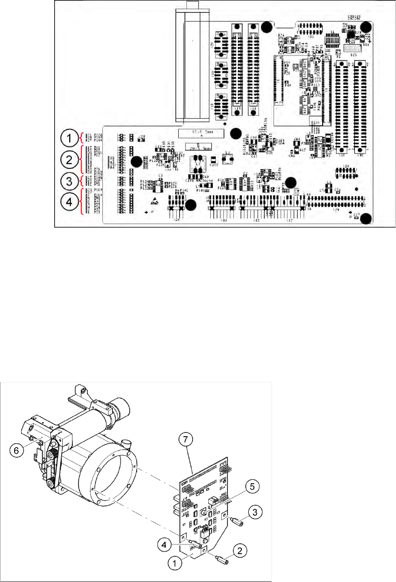
6.3.2.2 LEDs on gantry head distributor
Legend
Display functions and signals:
1. CAN signal
2. Power supply
3. Head Processor
4. LEDs C&P12
6.3.2.3 SP_12 Digital Intermediate Distributor [00330648-05]
6-9: Intermediate distributor
Legend
1. Intermediate distributor
2. Spacer bolt M3x10
3. Spacer bolt M3x10
4. Spacer bolt M3x10
5. Spacer bolt M3x10
6. Front section of C&P head
7. Connectors X1 and X2 (on the rear side)
The intermediate distributor (1) is fixed to the front
part (6) with four spacer bolts (items 2, 3, 4 and 5).
The pressure sensor is located above the spacer
bolts (5), on the back of the intermediate
distribution board. The cover of the intermediate
distributor is fixed with push buttons.