00195166-0402_SM_D4_EN.pdf - 第224页
Settings C&P12 Boards at C&P12 224 Serv ice Manual SIPLACE D4 The following supply voltages and signals are routed by the intermediate distributor to the individual placement head module s or to the head board: 6…
Settings
Boards at C&P12 C&P12
Service Manual SIPLACE D4
223
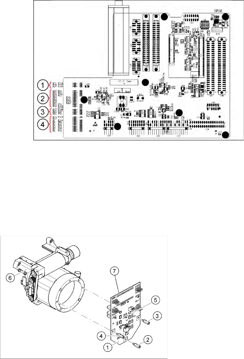
6.3.2.2 LEDs on gantry head distributor
Legend
Display functions and signals:
1. CAN signal
2. Power supply
3. Head Processor
4. LEDs C&P12
6.3.2.3 SP_12 Digital Intermediate Distributor [00330648-05]
6-9: Intermediate distributor
Legend
1. Intermediate distributor
2. Spacer bolt M3x10
3. Spacer bolt M3x10
4. Spacer bolt M3x10
5. Spacer bolt M3x10
6. Front section of C&P head
7. Connectors X1 and X2 (on the rear side)
The intermediate distributor (1) is fixed to the front
part (6) with four spacer bolts (items 2, 3, 4 and 5).
The pressure sensor is located above the spacer
bolts (5), on the back of the intermediate
distribution board. The cover of the intermediate
distributor is fixed with push buttons.
Settings
C&P12 Boards at C&P12
224 Service Manual SIPLACE D4
The following supply voltages and signals are routed by the intermediate distributor to the individual
placement head modules or to the head board:
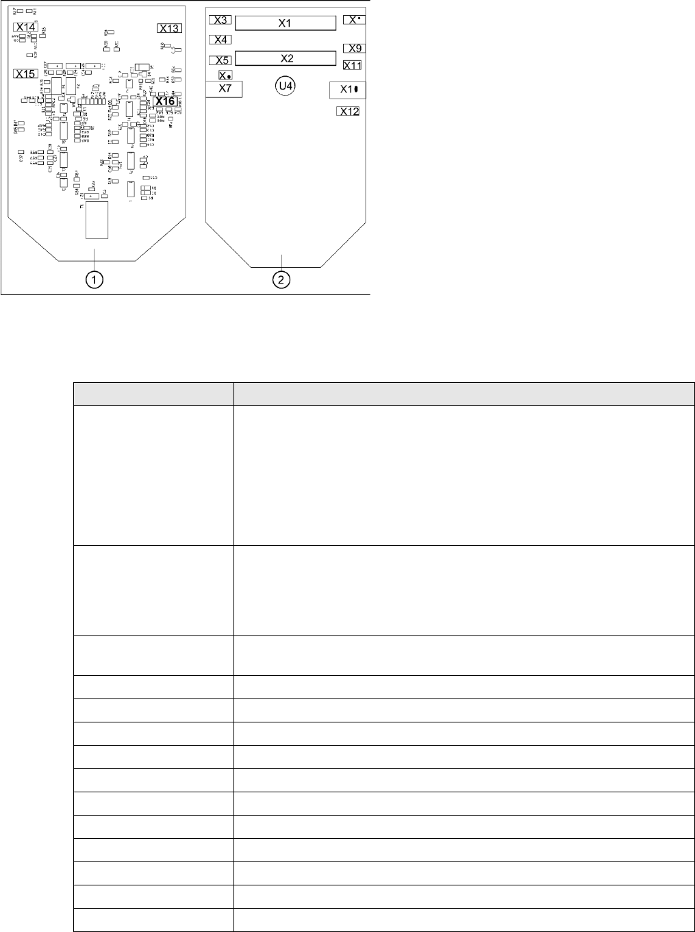
6-10: Position of the sockets
Legend
1. Front of the intermediate distributor
2. Back of the intermediate distributor
U4 = pressure sensor
Two 40-pin ribbon cables run from plug X1 and X2
on the intermediate distributor to socket X14 / X13
on the head board.
Connectors Description
X1, 40-pole Connected to plug X14 on the head board
Voltage supply, tacho and track signals for the Z axis drive
Signal from light barrier "Z axis in top position"
Signal from light barrier "Z axis in bottom position" (sensor stop signal)
Control signal for the air blast valve
Supply voltage +5 VDC, ±15 VDC
Reference point signal for the DP axis
Track signals for the DP axis
X2, 40-pole Connected to plug X13 of the gantry head distributor
Voltage supply and track signals for the star axis drive
Reference point for the star axis
Analog air blast pressure value
Supply voltages +5 VDC, ±15 VDC, +24 VDC
X3, 10-pole Connection for the Z motor and Z tacho signal (tacho signal is not used on the HF
machine)
X4, 10-pole Connection for the Z axis track signals
X5, 10-pole Connection for the star motor
X6, 6-pole Connection for the air blast valve
X7, 10-pole Connection for the DP axis track signals
X10, 10-pole Connection for the "Z axis up" signal
X11, 8-pole Connection for the light barrier "Z axis down" signal (sensor stop signal)
X12, 10-pole Connection for the star axis track signals
X13, 10-pole Test connection for the Z axis track signals
X14, 10-pole not used
X15, 10-pole Test connection for the star axis track signals
X16, 10-pole Test connection for the DP axis track signals

Settings
Overview of Settings on the C&P6/12 C&P12
Service Manual SIPLACE D4
225
6.3.3 Overview of Settings on the C&P6/12
Description Tools and equipment Settings
Mount the star onto the motor shaft
of the star motor
Adjust with the power pack and star
zero point gauge
Check the magnetic neutral position
in SITEST
(max. deviation 95 digits)
Determine zero point correction for
the star.
Gauge for zero point correction /
SITEST
Enter result of zero point correction
with SITEST
--> enter positions.
Switch position on star motor
(resolution of track signals 10 - 25)
None
HF/X/D machines at
switch position
(6.3.4 Setting the Resolution on
the Star Axis
J
226 ) 25
DP axis incremental encoder
adjustment to the glass scale
(segment)
Test probe 1.4 - 1.6 mm Distance 1.5 mm.
Adjustment mechanical position of
valve positioning drives
Distance gauge 0.2 mm or
adjustment plunger
0.2 mm distance plunger to the valve
housing
Light barrier Z axis down Test probe 1.0 mm Distance 1.0 mm.
Clamping device on Z belt --- Tension jack must lie on the belt
teeth at the top and bottom.
Belt tension of the Z axis Belt tension measurement device Belt tension 280 +/- 5 Hz
Z axis top stop Gauge for Z axis end stopper - star
gauge [03019865-xx]
Correct position is necessary to
determine the zero point correction.
Air blast tubes on the star Check with your eyes Check the distance between
incremental encoder and air blast
tubes.
Adjustment of air blast supply Feeler gauge Air blast tubes should be approx. 0.7
mm over the frame of the circular arc
guide
Adjustment of air blast placement Compressed air testing device 150 mbar on open 9x4 nozzle
Air blast setting on reject circuit Compressed air testing device 250 mbar
Belt tension setting for drive belt
replacement
DP belt adjustment aid Achieved with spring tension of tool