00195166-0402_SM_D4_EN.pdf - 第197页
Service W ork Replacing the Membrane (Vacuum Plate) on the Sleeve [00354244-xx] C&P12 Placement Head Service Manual SIPLACE D4 197 4.5.24 Replacing the Membrane (V ac uum Plate) on th e Sleeve [00354244-xx] The se al…
Service Work
C&P12 Placement Head Press Fit Connections with Fixture Clips on the Vision Board (D Series)
196 Service Manual SIPLACE D4
4.5.22 Press Fit Connections with Fixture Clips on the Vision Board (D Series)
4.5.23 Replacing the Raceway (Circular Arc Guide)
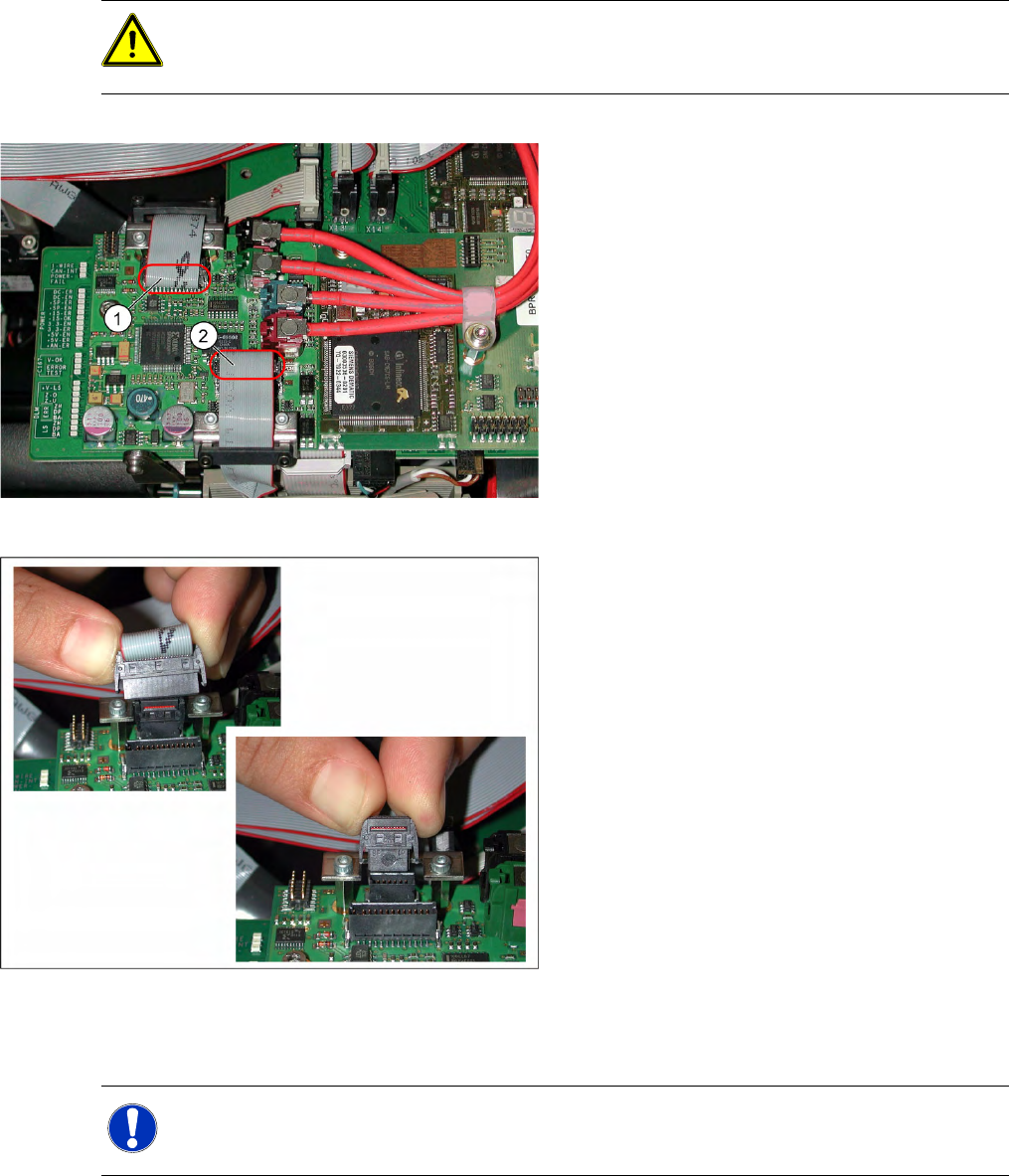
ATTENTION: Do not damage the fixture clips!
To disconnect the component and PCB camera connections, you need to open the fixture clips
by applying pressure to the side of the connector.
The adjacent diagram shows the press-fit
connections for the component camera (1) and the
PCB camera (2) on the Vision board of the
SIPLACE D1/D2. Each of the two positions has
two connectors of different sizes with fixture clips.
Z To release the press-fit connections, press the
connector sides together at the top, with your
thumb and index finger.
X The fixture clips will open and the connector
can be pulled up and off.
> The adjacent diagram shows the two press-fit
connections arranged one above the other, for
the Vision signals (small connector) and
illumination control (large connector) after
disconnection of the connectors.
NOTE:
This service task may only be performed by specially trained SIPLACE service technicians.
The procedure is described in a separate manual.
Service Work
Replacing the Membrane (Vacuum Plate) on the Sleeve [00354244-xx] C&P12 Placement Head
Service Manual SIPLACE D4
197
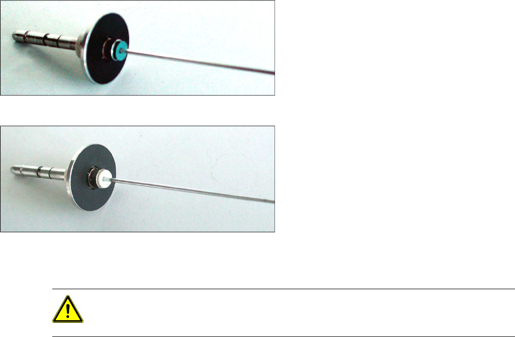
4.5.24 Replacing the Membrane (Vacuum Plate) on the Sleeve [00354244-xx]
The sealing membrane on the sleeves ensures sufficient vacuum by sealing the tip of the nozzle (serves
as the air inlet) in the sleeve.
Tools and Equipment
Standard tool
Spare part: membrane (vacuum plate) [00354244-xx]
Removal/Installation
X Loosen the old membrane with an Allen key (1.5 mm) and remove the membrane.
X Fit the new membrane onto the sleeve and tighten the membrane with an Allen key.
Blue membrane for the sleeve with ball fixing
C&P6/12
White membrane for the sleeve with ball fixing
C&P6/12, made of an alternative material
Expected release 10/2008
ATTENTION: Do not use a ball Allen key
X Make sure that you do not use a ball Allen key.
X The new, white version of the membrane should be available from 10/2008.
Service Work
C&P12 Placement Head Replacing the Vacuum Hoses on the C&P Head
198 Service Manual SIPLACE D4
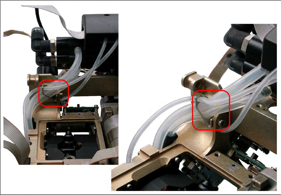
4.5.25 Replacing the Vacuum Hoses on the C&P Head
The length of the vacuum hoses and the way in which they are fitted has been improved to ensure that,
when the hoses are replaced - especially in X, D3 and HF machines - these hoses can be run in a
manner which will not interrupt the vacuum supply.
Tools and equipment
Standard tool
Spare part: vacuum hoses and guidance [03064147-xx]
Contents:
– Hose for placement circuit query (length new: 180 mm old: 190 mm) [03002187-02]
– Hose for hold circuit query (length new: 225 mm old: 200 mm) [03002188-02]
– Hose for placement circuit / 3x6x145 (length new: 145 mm old: 125 mm) [03010444-02]
– Hose for hold circuit / 4x7x140 [03010445S01]
– Hose guide [03048807-01]
– Cylinder screw M3x6 DIN912-A2 [03045028-01]
Removal/Installation
X Mark the connection points and the route of the individual hoses, so that these can be rerun correctly
later on.
X Disconnect the hoses from the vacuum generator and the vacuum measuring board.
X Fit the additional hose guide (M3 screw) on the top measuring hose duct.
X Fit the new hose as shown in the diagrams.