00195166-0402_SM_D4_EN.pdf - 第234页
Settings C&P12 Performing a Vacuum T est on the C&P 6/12 DLM Heads 234 Serv ice Manual SIPLACE D4 6.3.12 Performing a V acuum T est on the C&P 6/12 DLM Heads Damage to the valve plunger, silicone hose, the va…
Settings
Adjustment of air pressure values C&P12
Service Manual SIPLACE D4
233
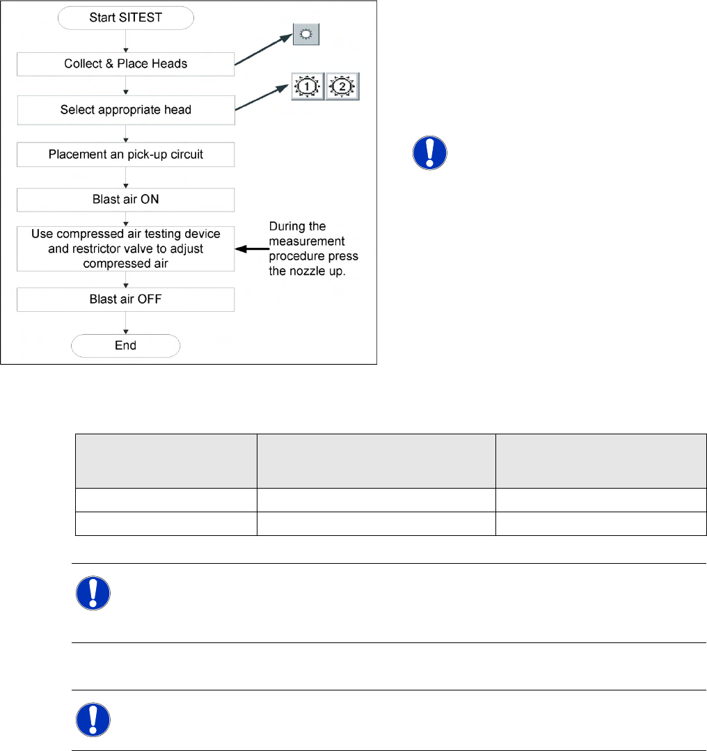
6.3.11.3 Setting the Air Blast Pressure Values with the Compressed Air Testing Device
Adjust to the values of the table below:
Repeat these adjustments several times, as the pickup / placement circuits are mutually dependent.
6-21: Flow chart determining air pressure values
When setting the air blast value with the
compressed air device and the adjustment valve,
observe the following:
X Press the nozzle upwards during the
measurement process!!
NOTE:
The air blast values which are shown in
the
Measured Air Blast
menu, on the
station computer screen, at
Single
Functions
or in the SITEST program,
do not reflect the air blast values really
set at the nozzle. They are used to
check that the air blast valve is
functioning correctly. Therefore, do not
use the values shown on the screen to
set the air blast. Instead, use only the
values determined with the
compressed air testing device.
Air Pressure Values Set with compressed air testing device
Measured at nozzle:
Displayed on the monitor:
(Only in pickup and placement
circuit)
pickup / placement circuit 150 mbar (100 - 200 mbar) e.g.: 250 mbar
Reject circuit 250 mbar (200 - 300 mbar) Reject circuit does not have a sensor
NOTE:
The two air blast circuits are controlled via a single valve and therefore influence one another
mutually. However, two different adjustment valves (see items 3 and 4 in the diagram above)
can be used to set the various pressures for each circuit.
NOTE:
Make sure the measurement sensor hose is fitted tightly on the nozzle.
Settings
C&P12 Performing a Vacuum Test on the C&P 6/12 DLM Heads
234 Service Manual SIPLACE D4
6.3.12 Performing a Vacuum Test on the C&P 6/12 DLM Heads
Damage to the valve plunger, silicone hose, the vacuum plate, in or on the nozzle can lead to leakage
which may then cause malfunctions during the placement process or which may reduce the vacuum
value in the holding circuit.
Vacuum test with normal nozzle
configuration
The vacuum tests for C&P6/12 in the station
software of the C&P12/6 placement heads
only checks the area from the vacuum
generator to the valve plungers.
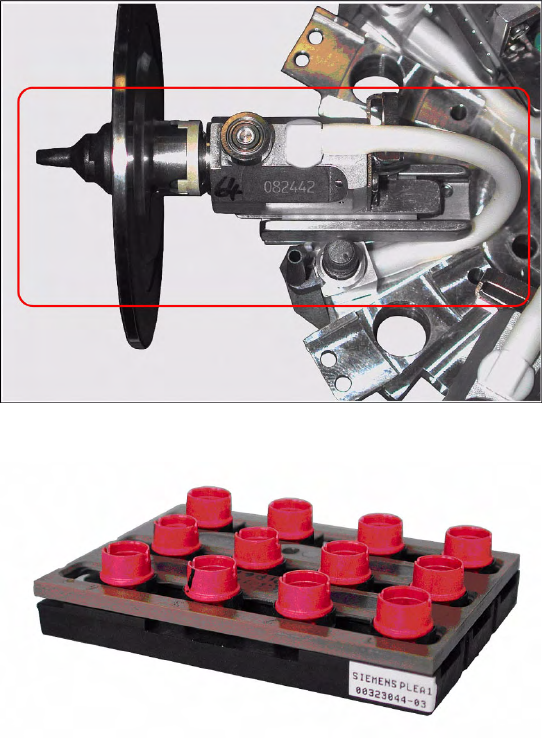
The area visible here (red frame), from the
valve plunger housing via the silicone hose
into the segment housing and through the
sleeve to the nozzle is not covered by the
normal vacuum test.
Equipment required
Closed nozzle tips are required for checking the
complete vacuum circuit.
The special nozzle use for this is marked red and
does not have a nozzle configuration on it:
SOKO nozzle for vacuum test DLM, Item No.
[03067029-01]
Settings
Performing a Vacuum Test on the C&P 6/12 DLM Heads C&P12
Service Manual SIPLACE D4
235
Vacuum test with closed nozzle
X Start SITEST and perform the first reference
run, if required.
X Select the gantry for the required vacuum test
on the C&P6/12 placement head.
X Place all the nozzles for the placement head in
the nozzle changer.
X Replace the full magazine at one magazine
position with the magazine holding the test
nozzles [03067029-01].
X Go to the Nozzle on head for segment 1 menu
and select the nozzle type which was originally
configured for this magazine position.
X Select the checkbox
All segments as
segment 1
X Pick up the vacuum test nozzles with all
segments.
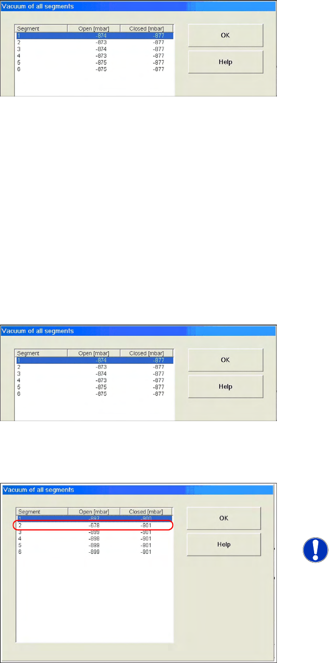
X Select the vacuum test menu and perform a
vacuum test.
X The error message
Vacuum difference open/
closed too low
can be ignored here.
As you can see in the measurement values
here, the
Open
values deviate by up to 3mbar
from the
Closed
values.
However, this is within the tolerance of 5
mbar, in which correct function can be reliably
assumed.
X If this tolerance value is exceeded, check the
valve plunger and vacuum plate and replace
these a a precaution, if necessary.
Scenario 1
Example of faulty vacuum values, which indicate a
damaged vacuum plate at segment 2 here.
NOTE: Irreparably damaged vacuum
plate
If both measurements for a particular
segment are around 640mbar, this
indicates that the vacuum plate is
irreparably damaged.