00195166-0402_SM_D4_EN.pdf - 第226页
Settings C&P12 Setting the Resolution on the Star Axis 226 Serv ice Manual SIPLACE D4 6.3.4 Setting the Resolu tion on the St ar Axis 6.3.5 Setting the Digit al Rota ry Encoder for the DP Axis Remove sleeve 1 and i…

Settings
Overview of Settings on the C&P6/12 C&P12
Service Manual SIPLACE D4
225
6.3.3 Overview of Settings on the C&P6/12
Description Tools and equipment Settings
Mount the star onto the motor shaft
of the star motor
Adjust with the power pack and star
zero point gauge
Check the magnetic neutral position
in SITEST
(max. deviation 95 digits)
Determine zero point correction for
the star.
Gauge for zero point correction /
SITEST
Enter result of zero point correction
with SITEST
--> enter positions.
Switch position on star motor
(resolution of track signals 10 - 25)
None
HF/X/D machines at
switch position
(6.3.4 Setting the Resolution on
the Star Axis
J
226 ) 25
DP axis incremental encoder
adjustment to the glass scale
(segment)
Test probe 1.4 - 1.6 mm Distance 1.5 mm.
Adjustment mechanical position of
valve positioning drives
Distance gauge 0.2 mm or
adjustment plunger
0.2 mm distance plunger to the valve
housing
Light barrier Z axis down Test probe 1.0 mm Distance 1.0 mm.
Clamping device on Z belt --- Tension jack must lie on the belt
teeth at the top and bottom.
Belt tension of the Z axis Belt tension measurement device Belt tension 280 +/- 5 Hz
Z axis top stop Gauge for Z axis end stopper - star
gauge [03019865-xx]
Correct position is necessary to
determine the zero point correction.
Air blast tubes on the star Check with your eyes Check the distance between
incremental encoder and air blast
tubes.
Adjustment of air blast supply Feeler gauge Air blast tubes should be approx. 0.7
mm over the frame of the circular arc
guide
Adjustment of air blast placement Compressed air testing device 150 mbar on open 9x4 nozzle
Air blast setting on reject circuit Compressed air testing device 250 mbar
Belt tension setting for drive belt
replacement
DP belt adjustment aid Achieved with spring tension of tool
Settings
C&P12 Setting the Resolution on the Star Axis
226 Service Manual SIPLACE D4
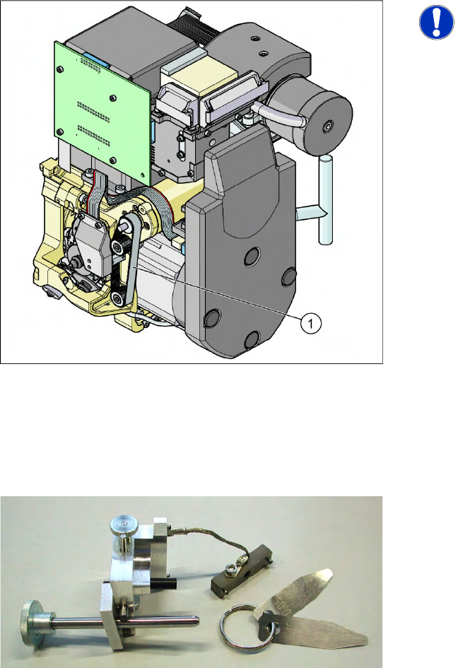
6.3.4 Setting the Resolution on the Star Axis
6.3.5 Setting the Digital Rotary Encoder for the DP Axis
Remove sleeve 1 and insert the star zero point gauge, in order to mechanically fix the star.
Now, remove sleeve 4 or the sleeve 2 for the 6 segment C&P head as well and align the encoder.
With the help of a parallel pin, set the rotary transducer of the DP - axis to 1.5 mm, parallel to the
glass pane of the segments.
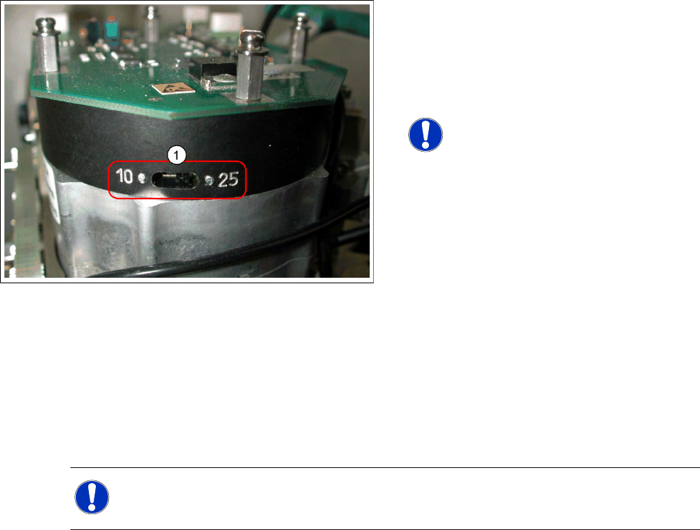
6-11: Setting the Resolution on the Star Axis
Legend
1. The switch for the star axis resolution is
directly beneath the C&P head on the star
motor.
X Check the setting of this switch (1).
NOTE:
Only set the switch if the machine
power is off.
HS-60, HS-50, S-27 HM, S-25 HM, S23 HM:
Switch position 10
D, HF/HF3 and X machines: Switch position
25
NOTE:
Make sure that a 1.4 mm test probe can be easily passed through and that a probe with 1.6 mm
can not be passed through.
Settings
Setting the Z axis Belt Tension C&P12
Service Manual SIPLACE D4
227
6.3.6 Setting the Z axis Belt Tension
6.3.7 Adjusting the Stop for the Z Axis
6.3.7.1 Tools and Equipment
6-12: Measurement point for belt tension
NOTE:
The measurement point on the
measurement head should be in the
middle, between two deflection pulleys.
The measurement head should be kept
at a distance of maximum 2 - 3 mm
from the toothed belt.
Legend
1. Measurement point for the belt tension
X Hold the measuring head of the belt tension
measuring device in front of the toothed belt
(1) .
X Strike the toothed belt, to stimulate a vibration
of the toothed belt.
X If the belt tension frequency does not match
the value 280 Hz ±10 Hz, tension or relax the
belt via the drive motor fastening.
X Repeat these instructions until the belt tension
is correct.
6-13: Gauge for Z end stopper
Set of DIN 911 Allen keys
Gauge for Z axis end stopper - star gauge
[03019865-xx]