00195166-0402_SM_D4_EN.pdf - 第139页
Service W ork Replacing the Light Barriers for Tr ansmitter and Receiver Modules [00370063] Modular Conveyor Service Manual SIPLACE D4 139 4.4.16.1 Replacing the T ransmitter or Receiver for Placement Areas 1 + 2 Receive…
Service Work
Modular Conveyor Replacing the Light Barriers for Transmitter and Receiver Modules [00370063]
138 Service Manual SIPLACE D4
4.4.16 Replacing the Light Barriers for Transmitter and Receiver Modules [00370063]
Parts
Please note the different item numbers for the individual light barriers - these are for the different lengths
of the connection cable.
Please consult the parts catalogue for the individual article numbers.
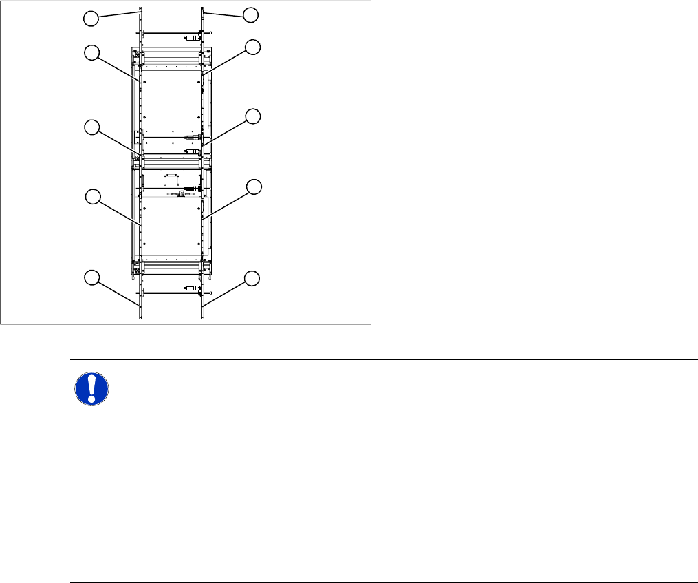
Overview
Legend
1. Transmitter at input conveyor
2. Receiver at input conveyor
3. Transmitter at placement area 1
4. Receiver at placement area 1
5. Transmitter at intermediate conveyor
6. Receiver at intermediate conveyor
7. Transmitter at placement area 2
8. Receiver at placement area 2
9. Transmitter at output conveyor
10. Receiver at output conveyor
10
9
8
7
1
6
5
4
3
2
NOTE: Important instructions for replacing the light barrier
The transmitters are installed on the moveable side of conveyor models, while the receivers are
on the fixed side (applies to the standard conveyor system, fixed side - right).
Check whether it would be helpful to feed in the new cable with the aid of the old one, at least
in some areas.
The connection plug is equipped with contacts, which are pressed onto the wires. You may find
it helpful to remove the contacts from the connection plug, in order to run the cable better
through openings.
For replacement purposes, the connection cable must be unthreaded as far as the relevant
conversion board of the conveyor side. This might be somewhat complicated depending on the
routing of cables inside the machine base.
X You may wish to contact SIPLACE Service re
garding this work or proceed as follows.
Service Work
Replacing the Light Barriers for Transmitter and Receiver Modules [00370063] Modular Conveyor
Service Manual SIPLACE D4
139
4.4.16.1 Replacing the Transmitter or Receiver for Placement Areas 1 + 2
Receiver:
X Remove the stop rail.
X Remove the short guide rail.
X Dismantle the holder and the receiver.
X Dismantle the receiver from the holder.
X Unthread the connection cable as far as the relevant conversion board of the conveyor side.
X Unplug the conversion board of the conveyor side.
X Rerun the connection cable accordingly and reconnect the conversion board of the conveyor side to
the power supply.
X Fix the receiver at the holder.
X Fix the holder, together with the receiver, to the base so that the holder lies flat on the base.
X Mount the short guide rail and align it.
X Mount the stop rail.
Transmitter:
X Dismantle the holder and the receiver.
X Dismantle the receiver from the holder.
X Unthread the connection cable as far as the relevant conversion board of the conveyor side.
X Unplug the conversion board of the conveyor side.
X Rerun the connection cable accordingly and reconnect the conversion board of the conveyor side to
the power supply.
X Fix the new light barrier in the original position.

Service Work
Modular Conveyor Replacing the Light Barriers for Transmitter and Receiver Modules [00370063]
140 Service Manual SIPLACE D4
4.4.16.2 Replacing the Transmitter or Receiver for the Input or Output Conveyor
Receiver:
X Remove the stop rail.
X Remove the short guide rail.
X Dismantle the holder and the receiver.
X Dismantle the receiver from the holder.
X Unthread the connection cable as far as the relevant conversion board of the conveyor side.
X Unplug the conversion board of the conveyor side.
X Rerun the connection cable accordingly and reconnect the conversion board of the conveyor side to
the power supply.
X Fix the receiver at the holder.
X Fix the holder, together with the receiver, to the base so that the holder lies flat on the base.
X Mount the short guide rail and align it.
X Mount the stop rail.
Transmitter:
X Dismantle the holder and the receiver.
X Dismantle the receiver from the holder.
X Unthread the connection cable as far as the relevant conversion board of the conveyor side.
X Unplug the conversion board of the conveyor side.
X Rerun the connection cable accordingly and reconnect the conversion board of the conveyor side to
the power supply.
X Fix the new light barrier in the original position.
NOTE:
The transmitters on the input and output conveyors are freely accessible. The bracket must be
loosened and the screws fastening the light barrier removed.
X
NOTE:
Otherwise check whether you can run the cable through the opening by removing the contacts
in the connection plug.