00195166-0402_SM_D4_EN.pdf - 第167页
Service W ork Replacing the Valve Positioning Drive for the Reject Circuit [00 367768] C&P12 Placement Head Service Manual SIPLACE D4 167 4.5.9.1 New V alve Posit ioning Drives (From V ersion 03) 4.5.9.2 Mechanical A…
Service Work
C&P12 Placement Head Replacing the Valve Positioning Drive for the Reject Circuit [00367768]
166 Service Manual SIPLACE D4
Installation
See also:
J
6.3.1 Calibrating the C&P Head and Cameras [
J
221]
Legend
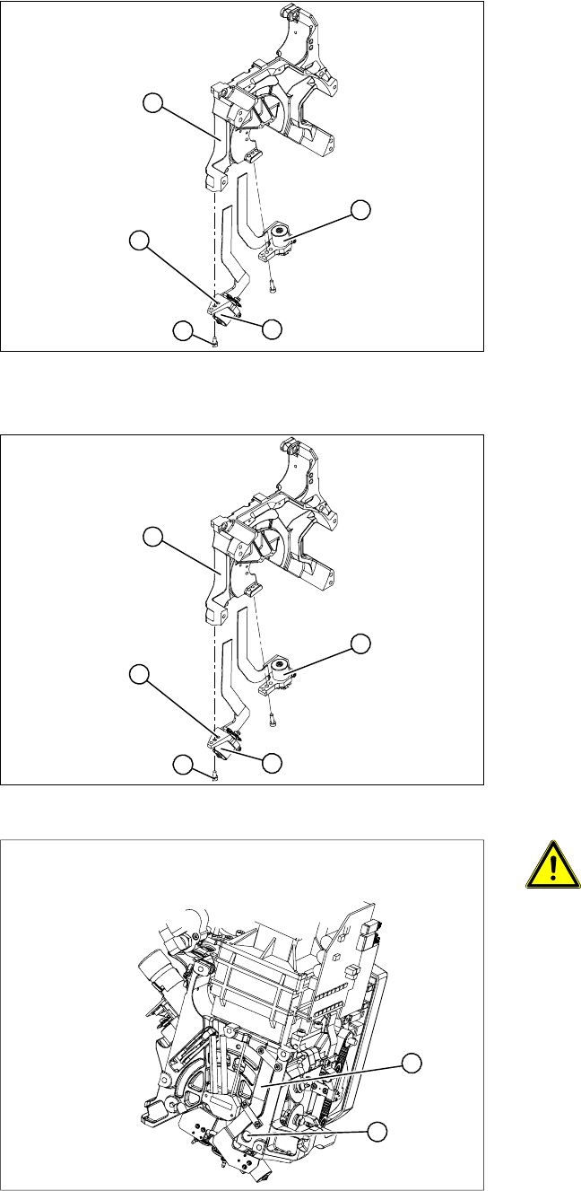
1. Valve positioning drive for the placement
circuit [00368075]
2. Valve positioning drive for the reject circuit
[00367768]
X Loosen the fastening screw (4).
X Carefully remove the valve positioning drive
(2).
5
1
4
3
2
X Insert the valve positioning drive. Make sure
that it is seated correctly on the parallel pins
(5).
X Loosely screw in the hexagon socket-head
screw (4)
X Use the cable clamps to fix the ribbon cable in
position. Make sure that the ribbon cables are
not pinched.
5
1
4
3
2
ATTENTION: Check how the cables
are run!
Check that the ribbon cables are laid
correctly (1).
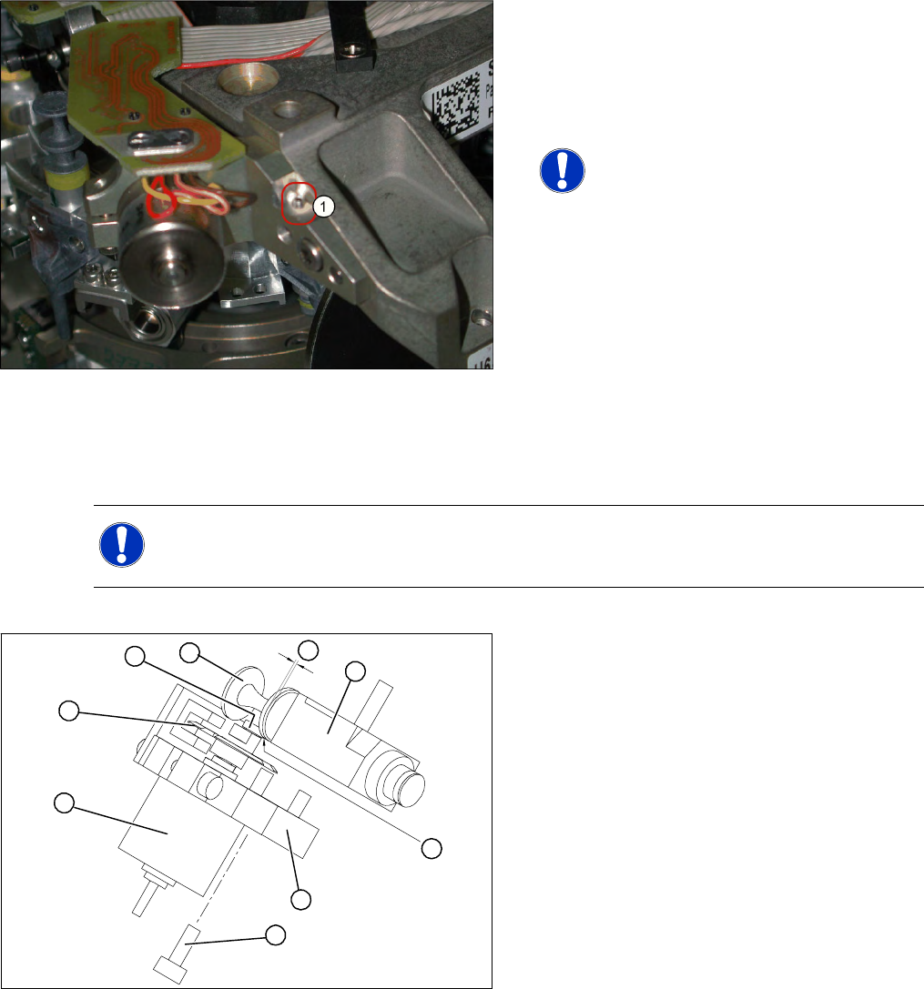
X The flat ribbon cable for the two
valve positioning units must be run
outside the holes (2). otherwise it will
be damaged when the C&P head is
fitted onto the head plate.
1
2
Service Work
Replacing the Valve Positioning Drive for the Reject Circuit [00367768] C&P12 Placement Head
Service Manual SIPLACE D4
167
4.5.9.1 New Valve Positioning Drives (From Version 03)
4.5.9.2 Mechanical Adjustment (Up To Version 02)
4-47: New valve positioning drive holder for the reject position (DLM2/3) with
position locking function
These valve positioning drives replace the
previous versions on the DLM2/3 placement head.
For precise alignment and adjustment of the
drives, use the new tool which replaces the
distance gauge 0.2 mm [00325445-01].
NOTE:
This holder also fits the valve
positioning drive on the placement and
reject position of the DLM1 placement
head. A second 1.4 mm thread (1) is
provided on the opposite side for this
purpose.
NOTE:
Instead of using the adjustment valve plungers, the DLM1 and DLM2 heads can also be set with
the distance gauge.
Legend
1. Stepping motor
2. Cam disk
3. Deep-groove ball bearings
4. Valve plunger
5. Valve casing
6. M3x10 hexagon socket-head screw
7. Valve positioning drive (flange)
B
A
1
7
6
5
4
3
2
Service Work
C&P12 Placement Head Replacing the Valve Positioning Drive for the Reject Circuit [00367768]
168 Service Manual SIPLACE D4
X Use the feeler gauge to set the distance
between the valve plunger and valve casing to
0.2 mm (A).
X Turn the cam disk (2) until the deep-groove
ball bearings (3) point towards the valve
casing.
X Move the valve positioning drive (7) so that the
deep-groove ball bearings (3) come into
contact with the valve plunger (4) at position
(B).
X Use the hexagon socket-head screw to fix the
adjustment unit in this position (6).
X Fit the C&P head.
X Use the SITEST program to test that the valve
positioning drive is functioning correctly.
X Use the SITEST program to calibrate the C&P
head.
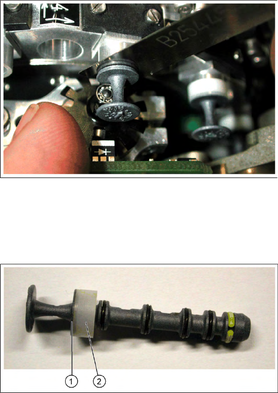
4-48: Valve plunger version 03 (C&P12: [00351498-03], C&P6: [00351500-
03])
X If the new valve plungers are used (s. diag. on
left) proceed as follows:
Take out one valve plunger and remove the
sleeve (2).
Insert the plunger without bushing and carry
out the following steps on this segment:
X Insert the distance gauge (0.2 mm) between
valve plunger and valve casing.
X Rotate the valve positioning drive 90 degrees
from its initial position. The eccentric of the
valve adjustment drive will just touch the inner
side (1) of the valve plunger.
X Fix the motor of the valve drive in this position.
X Remember to replace the tube on the valve
plunger.