00195166-0402_SM_D4_EN.pdf - 第187页
Service W ork Replacing the RSF Digital Rotary Encoder (DP Axis) [0 0335990-xx] C&P12 Placement Head Service Manual SIPLACE D4 187 4.5.19 Replacing the RSF Digit al Rota ry Encoder (DP Axis) [00335990-xx] Removal Ins…
Service Work
C&P12 Placement Head Replacing the Star Drive [03020626-xx]
186 Service Manual SIPLACE D4
4.5.18 Replacing the Star Drive [03020626-xx]
Removal
Installation
See also:
J
6.3.9 Determining the Zero Point Correction for the Star Axis of the C&P Head [
J
230]
Legend
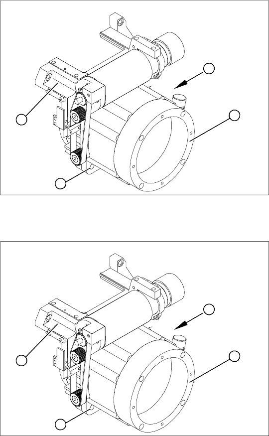
1. Star drive, digital / DLM3
2. 4 x M5x16 hexagon socket-head screws
3. Front section of C&P head
(A) Connecting cable for the star drive
X Dismantle the intermediate distributor.
X Dismantle the front part of the C&P head.
X Dismantle the star.
X Loosen the four M5x16 hexagon socket-head
screws (2).
X Lift the star drive off the front part of the C&P
head.
A
1
3
2
X Place the star motor onto the front part of the
C&P head, so that the star drive connection
cable points to the position marked (A).
X Fix the star drive in place with the four M5x16
hexagon socket-head screws (2).
X Fit and adjust the star. (See zero point
correction.)
X If you are unable to adjust the zero point
correction correctly, loosen the 4 star motor
screws and rotate the star motor in the
required direction, within the tightening
tolerance.
X Fit the front part of the C&P head.
A
1
3
2
Service Work
Replacing the RSF Digital Rotary Encoder (DP Axis) [00335990-xx] C&P12 Placement Head
Service Manual SIPLACE D4
187
4.5.19 Replacing the RSF Digital Rotary Encoder (DP Axis) [00335990-xx]
Removal
Installation
Legend
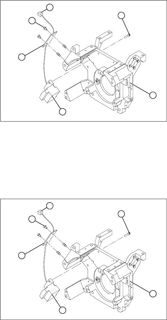
1. Front section of C&P head
2. RSF digital rotary encoder 12/DLM3
3. 2 x M2.5x8 hexagon socket-head screws 2 x
4. RSF board, type 950
5. 2 x M2.5x4 hexagon socket-head screws 2 x
6. Plug connector in the slot on the intermediate
distributor
X Dismantle the front part of the C&P head.
X Remove the black blanking cap over the RSF
board (4).
X Remove the plug connector (6) from the slot
on the intermediate distributor.
X Loosen the two M2.5x4 hexagon socket-head
screws (5) for fixing the RSF board.
X Dismantle the handle of the C&P head.
X Loosen the two M2.5x8 hexagon socket-head
screws (3) and remove the digital encoder.
1
6
5
4
3
2
X Insert the new rotary encoder and initially fix
loosely in place with the two M2.5x8 hexagon
socket-head screws (3).
X Fit the handle of the C&P head.
X Insert the sleeve into the star and turn the star,
with the sleeve, until it reaches the rotary
encoder.
X Fix the star in this position using the gauge for
the star.
1
6
5
4
3
2
Service Work
C&P12 Placement Head Replacing the RSF Digital Rotary Encoder (DP Axis) [00335990-xx]
188 Service Manual SIPLACE D4
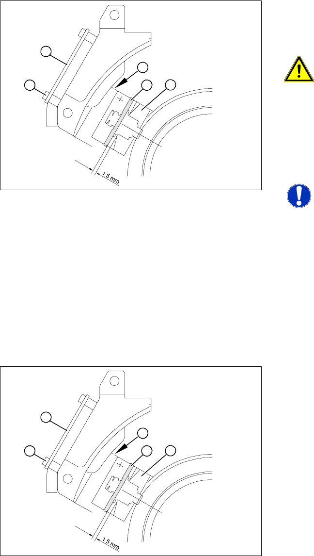
X Adjust the rotary encoder, so that the distance
between the rotary encoder window and the
incremental disk on the sleeve is 1.5 mm.
Proceed as follows:
ATTENTION: Sensitive component!
RISK OF BREAKING THE
INCREMENTAL DISK
X Carefully push the tapered end of the test
probe between the window of the incremental
encoder (1) and the incremental disk (2).
X Loosen the fixing screws for the incremental
encoder, if you can not push the test probe in
easily.
NOTE:
The test probe has a blunt and a
tapered end. Only push the tapered
end of the test probe between the
incremental encoder and incremental
disk of the sleeve, to avoid scratching
the disk and thus causing counting
errors.
X Carefully push the rotary encoder towards the
incremental disk and along the stop edge (A)
until the test probe lies flat against the
incremental disk (2) and the window of the
rotary encoder (1).
A
1
4
3
2
X Fix the rotary encoder in place using the two
M2.5x8 hexagon socket-head screws.
X Carefully pull the test probe out of the gap.
X Remove the gauge for the star.
X Remove the sleeve from the star.
X Use the two M2.5x4 hexagon socket-head
screws (4) to fasten the RSF board (3).
X Connect the plug connector to the slot on the
intermediate distributor.
X Place the black blanking cap over the RSF
board.
X Fit the front part of the C&P head.
X Use the SITEST program to check that the
rotary encoder is working correctly.
A
1
4
3
2