IPC-4556 印制板化学镍钯浸金(ENEPIG)规范ENG.pdf - 第13页
if the end use environment is considered harsh. For additional information on ENEPIG corrosion resistance to MFG, see Appendix 11. 1.4.7.2 High Frequency Signal Loss Higher frequency (>3 GHz) applications may experien…

nickel and the gold mitigates the potential for hyper-corrosion of the electroless nickel deposit, thus enhancing its solder-
ability and solder joint reliability. The minimal thicknesses of the electroless palladium and of the immersion gold deposit
make the possibility of embrittlement of the solder joint by palladium or gold negligible. It is the responsibility of the user
to calculate the percentage of both gold and palladium in the resulting solder joint where mounting pad sizes associated with
0201 or smaller components are encountered and compare these calculated levels of gold or palladium to the 3% threshold
values believed to give rise to solder joint embrittlement.
1.4.2 Wire Bonding The second primary function of ENEPIG is to provide a wire bondable surface finish suitable for
gold, aluminum and copper wire applications. ENEPIG has been found to meet the requirements of MIL-STD-883, Method
2011.8. The committee has performed extensive testing with gold wire (see APPENDIX 8) and has received additional anec-
dotal data from members confirming the suitability of this finish for aluminum and copper wirebonding. Variables that are
likely to affect performance include cleanliness, substrate materials, wire thickness and substrate copper surface roughness,
as ENEPIG deposits are not capable of completely levelling the substrate surface. During the development of this specifi-
cation, surface roughness values of up to an Ra value of 389 nm have been tested with no negative impacts on gold wire
bond strength.
1.4.3 Contact Surface There is a substantial amount of experience using ENEPIG for the applications listed below in
1.4.3.1 and 1.4.3.2.
1.4.3.1 Membrane Switches ENEPIG is a de facto standard for soft touch membrane switches.
ENEPIG plated samples tested for 2 million contact actuations showed negligible change in contact resistance. For these
actuations, the average deposit thicknesses were nominally: 4.65 µm [183 µin] of electroless nickel (EN), 0.13 µm [5.2 µin]
of electroless palladium (EP) and 0.053 µm [2.1 µin] of immersion gold (IG).
Note: This test was run to the full number of cycles with no visible impact on the ENEPIG deposit.
1.4.3.2 Metallic Dome Contacts ENEPIG has been demonstrated to be suitable for use with metallic (stainless steel), cir-
cular dome contacts, based on testing to 1 million cycles. For this testing, the ENEPIG was deposited at nominal thicknesses
of 5.38 µm [212 µin] of electroless nickel (EN), 0.081 µm [3.17 µin] of electroless palladium (EP) and 0.015 µm [0.58 µin]
of immersion gold (IG).
Note: The committee continues to be interested in any additional test data using other metals and contact shapes for this
particular application.
1.4.4 EMI Shielding ENEPIG can be used as a surface finish at the interface between electromagnetic interference (EMI)
shielding materials and printed boards (PBs).
1.4.5 Interface for Conductive and/or Anisotropic Adhesives ENEPIG is suitable for use as an interface for conductive
adhesives used as an alternative to solder. It is also suitable for anisotropic adhesive applications.
1.4.6 Connectors
1.4.6.1 Press-Fit Applications
Press-fit performance for compliant pin applications should meet Telcordia GR-1217-
CORE, MIL-C-28859 or equivalent. Excessive electroless nickel thicknesses can lead to concerns with excessive press-fit
insertion forces. The additional thickness of the palladium specified either by this specification and/or a customer-specific
requirement should be added to the electroless nickel thickness fit calculation when considering the type of application.
1.4.6.2 Edge Tab Contact Applications The ENEPIG surface finish is suitable for plug-to-install applications (twenty
insertions/withdrawals or less) using low insertion force (LIF) or zero insertion force (ZIF) connectors. ENEPIG is not
believed to be suitable as a surface finish for edge connectors that require multiple insertion/withdrawals (more than twenty)
or high insertion force applications. This application generally requires an alternate metallic finish, such as electrolytic hard
gold.
1.4.7 Limitations of ENEPIG
1.4.7.1 Creep Corrosion/Chemical Resistance
ENEPIG, similar to the other alternate surface finishes addressed by the
IPC-455X series specifications, is susceptible to creep corrosion in high sulfur and/or chlorine-containing atmospheres that
are commonly also at high temperature and humidity. While mixed flowing gas (MFG) tests per Battelle Class 2 conditions
have been performed and show sustained solderability with ENEPIG, it is recommended to test specific design/applications
IPC-4556 January 2013
2

if the end use environment is considered harsh. For additional information on ENEPIG corrosion resistance to MFG, see
Appendix 11.
1.4.7.2 High Frequency Signal Loss Higher frequency (>3 GHz) applications may experience signal loss on full build
(i.e., where ENEPIG is applied over both traces and pads) designs. Signal loss is minimal when only the pads (but not the
traces) are plated with the finish.
2 APPLICABLE DOCUMENTS AND TERMS AND DEFINITIONS
2.1 IPC
1
J-STD-003 Solderability Tests for Printed Boards
IPC-1601 Printed Board Handling and Storage Guidelines
IPC-2221 Generic Standard on Printed Board Design
IPC-6011 Generic Performance Specification for Printed Boards
IPC-6012 Qualification and Performance Specification for Rigid Printed Boards
IPC-6013 Qualification and Performance Specification for Flexible Printed Boards
IPC 5704 Cleanliness Requirements for Unpopulated Printed Boards
IPC-TM-650 Test Methods Manual
2
2.3.25 Detection and Measurement of Ionizable Surface Contaminants by Resistivity of Solvent Extract (ROSE)
2.4.1 Adhesion, Tape Testing
2.6.3.5 Bare Board Cleanliness by Surface Insulation Resistance
2.6.14.1 Electrochemical Migration Resistance Test
2.2 American Society for Testing and Materials (ASTM International)
3
ASTM B568 Standard Test Method for Measurement of Coating Thickness by X-Ray Spectrometry
ASTM B733 Standard Specification for Autocatalytic (Electroless) Nickel-Phosphorus Coatings on Metal
ASTM B827 Standard Practice for Conducting Mixed Flowing Gas Environmental Tests
ASTM B845 Standard Guide for Mixed Flowing Gas Tests for Electrical Contacts
2.3 JEDEC
4
JESD 213 Common Test Method for Detecting Component Surface Finish Materials
2.4 Defense Standardization Program
5
MIL-STD-883 Method 2011.7 Test Method Standard, Microcircuits - Bond Strength (Destructive Bond Pull Test)
MIL-STD-1580 Department of Defense Test Method Standard (Destructive Physical Analysis for Electronic, Electro-
magnetic, and Electromechanical Parts)
MIL-C-28859 General Specification for Connector Component Parts, Electrical Backplane, Printed-Wiring
2.5 Telcordia Technologies, Inc.
6
Telcordia GR-1217-CORE Generic Requirements For Separable Electrical Connectors Used In Telecommunications Hard-
ware
2.6 International Organization for Standardization (ISO)
7
ISO-4527 Auto-Catalytic Nickel-Phosphorous Coatings; Specifications and Test Methods, Annex A: Determination of Coat-
ing Thickness and Annex D: Determination of Coating Composition (Nickel and Phosphorous Content).
1. www.ipc.org
2. Current and revised IPC Test Methods are available on the IPC Web site (www.ipc.org/html/testmethods.htm)
3. www.astm.org
4. www.jedec.org
5. www.dsp.dla.mil
6. www.telcordia.com
7. www.iso.org
January 2013 IPC-4556
3
2.7 Terms, Definitions and Acronyms The definition of all terms used herein shall be as specified in IPC-T-50 and as
defined below:
MTO (Metal Turnover) – A measure of electroless or immersion plating bath ‘‘age,’’ MTO is a period of operation during
which the sum of the periodic replenishments of the metal being deposited is equal to the amount of metal in the initial bath
makeup. For example, if the metal concentration in an electroless bath is 5 grams per liter and the bath is 100 liters in size,
then one MTO is the period of useage during which 500 grams of metal is added back into the bath by replenishment as the
metal is actively being deposited out of the bath. Depending on how heavily an electroless or immersion bath is being
‘worked’, the time taken for one MTO may range from as little as a few hours to a week or more. It is common for an
electroless or immersion plating bath to last for multiple MTOs before being removed from service and fully replaced.
3 REQUIREMENTS
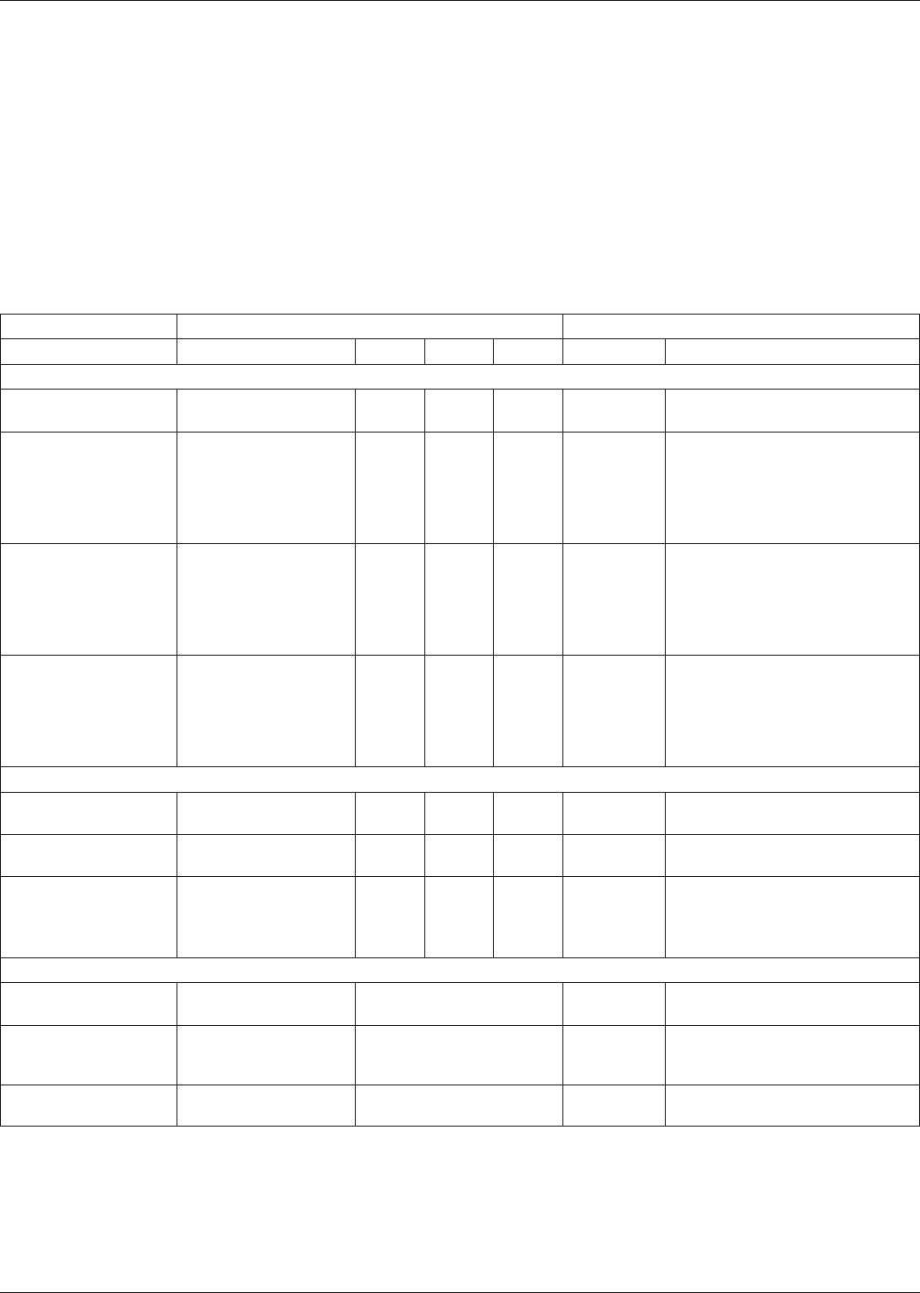
Table 3-1 Requirements of Electroless Nickel Electroless Palladium Immersion Gold (ENEPIG) Plating
Inspection Class/Test Frequency (A.Q.L.) Requirements
Tests Test Method 1 2 3/3A Paragraph Remarks
General:
Visual Visual 4.0 2.5 1.0 3.1
Uniform color and complete
coverage of surface to be coated.
Electroless Nickel
Thickness
Appendices 4 and 9 6.5 4.0 2.5 3.2.1
3 to 6 µm [118.1 to 236.2 µin] at
± 4 sigma (standard deviations)
from the mean as measured on
a nominal pad size of 1.5 mm x
1.5 mm [0.060 in x 0.060 in] or
equivalent area.
Electroless Palladium
Thickness
Appendices 4 and 9 6.5 4.0 2.5 3.2.2
0.05 to 0.30 µm [2 to 12 µin] at
± 4 sigma (standard deviations)
from the mean as measured on
a nominal pad size of 1.5 mm x
1.5 mm [0.060 in x 0.060 in] or
equivalent area.
Immersion Gold
Thickness
>0.030µm [1.2 µin] a
Appendices 4 and 9 6.5 4.0 2.5 3.2.3
t - 4 sigma
(standard deviations) below the
mean as measured on a nominal
pad size of 1.5 mm x 1.5 mm
[0.060 in x 0.060 in] or equivalent
area.
Physical:
Adhesion/Tape Test
IPC-TM-650,
Method 2.4.1
6.5 4.0 4.0 3.4
No evidence of plating and/or
solder mask removed.
Solderability J-STD-003 4.0 2.5 2.5 3.5
Refer to the applicable
performance specification.
Force Measurement -
When required, the
specified provisions
apply:
Force Measurement
Test
4.0 2.5 2.5 3.5.1
0.14 mN/mm minimum for
Eutectic SnPb testing.
0.19 mN/mm minimum for SAC
305 testing.
Environmental:
Cleanliness IPC- 5704
When tests required, AQL
shall be AABUS
3.6
Refer to applicable performance
specification.
SIR
IPC-TM-650,
Method 2.6.3.5;
GR78-Core
When tests required, AQL 3.6
shall be AABUS 3.6
1.0E+08 ohms
1.0E+10 ohms
Electrolytic Corrosion
IPC-TM-650,
Method 2.6.14.1
When tests required, AQL
shall be AABUS
3.7 AABUS
IPC-4556 January 2013
4