IPC-4556 印制板化学镍钯浸金(ENEPIG)规范ENG.pdf - 第69页
The electroless nickel and immersion gold surface finish thickness metal layers were selected as a control; the electroless palladium thickness and wire bond pad surface roughness were the variables chosen by consensus of…
APPENDIX 8
Gold Wire Bonding
Stephen Meeks
St Jude Medical
The tasks identified by a consensus of the IPC 4-14 Plating Processes Subcommittee members to evaluate the suitability of
the Electroless Nickel Electroless Palladium Immersion Gold ENEPIG) plating finish for wire bondability were as follows:
• Round Robin Task Group Members Roles and Responsibilities
• Development of a Wire Bond Test Vehicle
• Commercial ENEPIG Plating Finish Supplier Contributions
• ENEPIG Plating Finish Attributes Selected to Evaluate Wire Bonding
• 1 mil Gold Ball Wire Bonding and Destructive Pull Testing Evaluations per MIL-STD-883
Round Robin Task Group Member Roles and Responsibilities
The wire bond test vehicle artwork was supplied by Kulicke and Soffa (K&S).
Fabrication of the test vehicles was performed by TTM Technologies, Inc.
Commercial suppliers provided the ENEPIG plating finish test vehicles.
St. Jude Medical conducted the auto wire bonding and destructive pull testing evaluations.
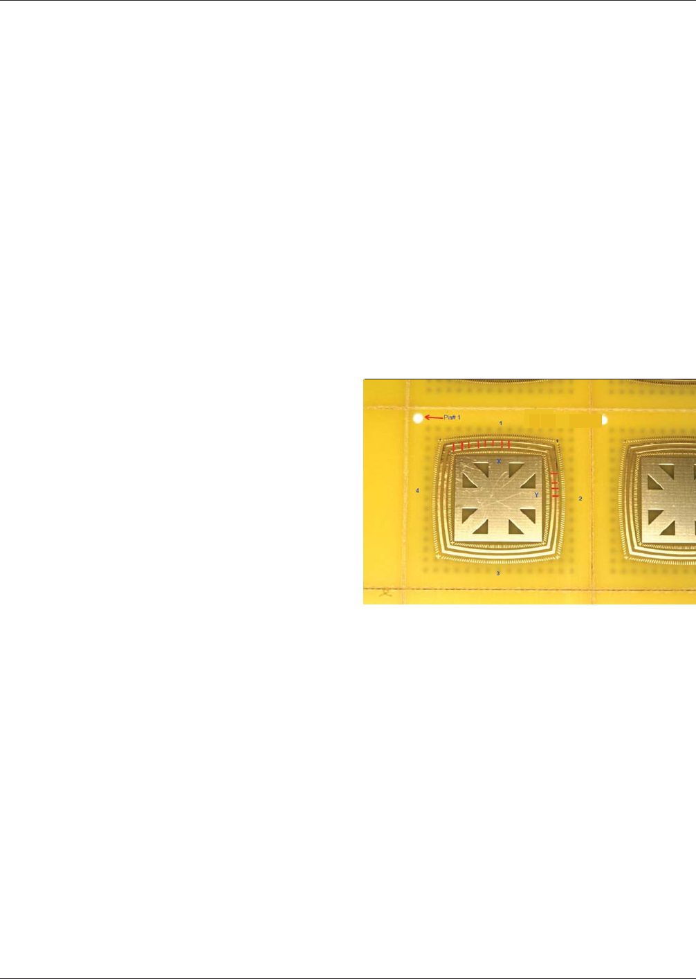
Development of the Wire Bond Test Vehicle The artwork
for the round robin wire bond test vehicle was provided by
K&S. The test vehicle/coupon was a double sided Printed Cir-
cuit Board (PCB) with no inner planes. The dimensions of an
individual test coupon were 1 inch by 1 inch square and 0.034
inches thick. The coupon was designed for wire bonding to be
conducted only on one side of the part. Two levels of wire
bond pad surface roughness were selected for the test matrix –
high and low.
FR-4 was the laminate material used for the test vehicle. No
solder mask was incorporated. All coupons were fabricated by
TTM. A tooling hole was added to each coupon within the
panel to provide for a pin #1 location. The wire bonding areas
of each coupon were separated into 4 quadrants for wire bond-
ing and accurate destructive pull data tracking (as shown in
Figure A8-1).
Commercial ENEPIG Plating Finish Suppliers Following the fabrication of the ENEPIG panels by TTM, the panels con-
taining the wire bond test coupons were shipped to the following commercial ENEPIG finish suppliers who had agreed to
participate in the Round Robin testing:
1. Uyemura
2. DOW Electronic Materials
3. MacDermid
4. Enthone-Cookson
5. OMG
6. Atotech
Figure A8-1 Wire Bond Test Vehicle Showing pin #1, quad-
rants 1, 2, 3 and 4.
Note: The red lines indicate the general wire bond locations and sites
used for Destructive Pull Testing (DPT).
IPC-4556 January 2013
NiPdAu
1 -mil
Gold
Wire
58
Bonding
The electroless nickel and immersion gold surface finish thickness metal layers were selected as a control; the electroless
palladium thickness and wire bond pad surface roughness were the variables chosen by consensus of the subcommittee for
evaluation of the suitability of ENEPIG as a plating finish for gold wire bonding.
The electroless palladium thickness layer varied based upon the following target thicknesses:
a. 4 micro inches
b. 8 micro inches
c. 12 micro inches
d. 20 micro inches
ENEPIG Plating Finish Attributes Used to Evaluate 1-Mil Gold Wire Bonding 1 mil gold ball auto wire bonding for evalu-
ation of the ENEPIG finish was based upon using the established volume manufacturing wire bond processes used at St. Jude
Medical (Scottsdale, AZ). Experienced and certified wire bond associates and technicians performed all wire bond setups,
calibrations and conducted the actual wire bonding of the ENEPIG test vehicles.
The wire bond testing was configured as a blind test. The suppliers, plating thicknesses and other properties were unknown
before and after actual processing. Twenty-one (21) groups of panels were received with special labeling used for designa-
tion of the coupons and wire bonding data collection (Table A8-I).
Development of 1 mil gold wire bond parameters and attributes used for wire bonding onto the coupons with the ENEPIG
plating finish was consistent with the same approaches used to establish auto wire bonding parameters for standard electro-
lytic gold plating finish substrates.
Auto Wire Bond Process Design Point Areas of Focus Included:
• Preheat Stage Temperature
• Power / Force / Time
• Visual Inspection Before and After Wire Bonding
• Selection of Coupons within the Panels
• One Set of Parameters to be used for ALL Wire Bond Samples (Standardization Target)
• No Effort would be Placed into ‘‘Making Wires Stick’’
• Wire Bond Equipment was Calibrated Before Processing
• Certified Wire Bond Operators Used for Wire Bonding
• 1 mil Diameter Gold Wire Used for Bonding
• Destructive Pull Testing per MIL-STD-883 Would be Incorporated
• Pre-conditioning of Test Vehicle Before Wire Bonding
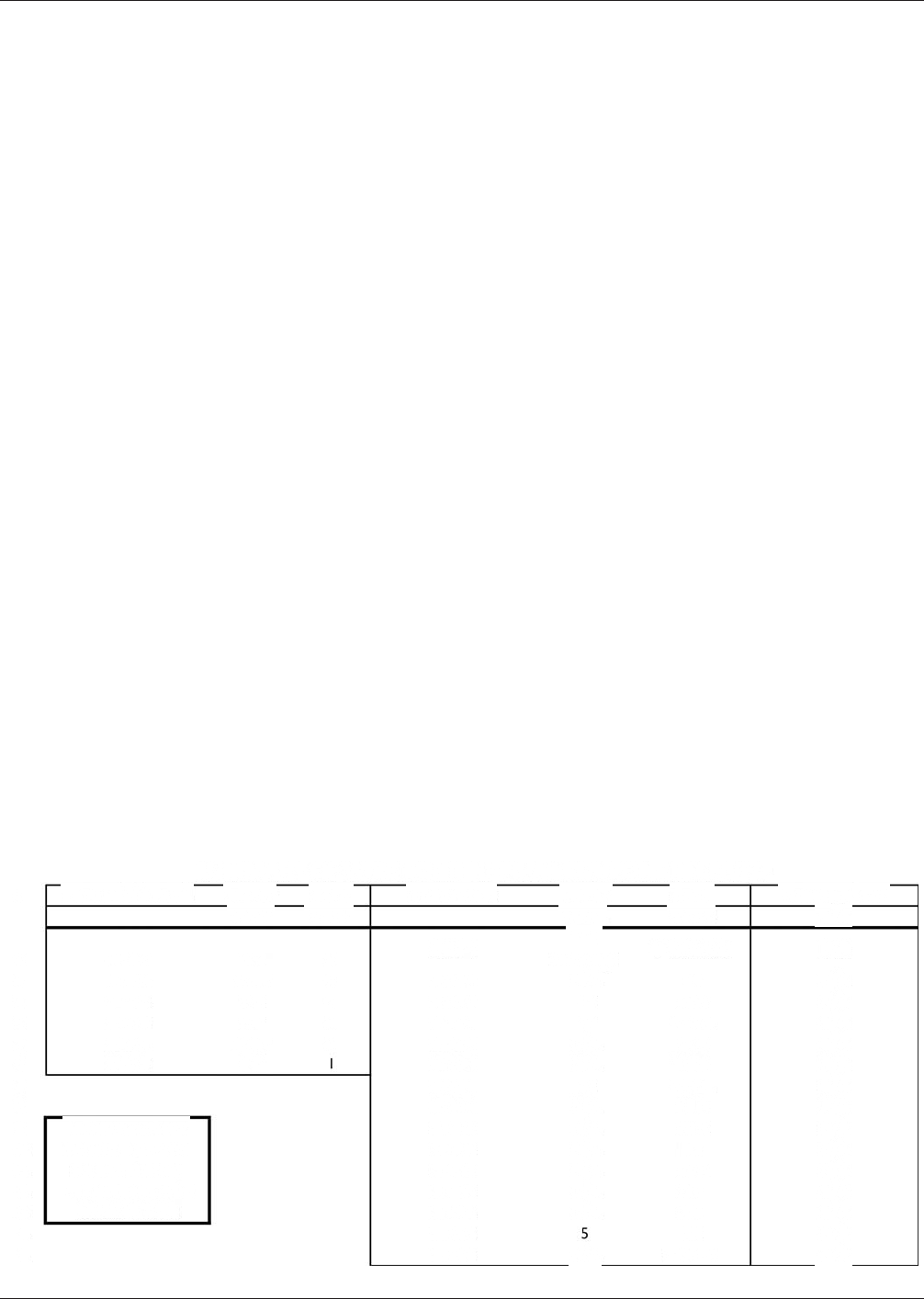
Table A8-I Twenty-one Panels Marked (a) Whole Panel, (b) Array and (c) Hand Cut
January 2013 IPC-4556
59
ID
1
2
3
4
5
6
7
8
9
10
11
12
13
14
15
SUMMARY OF WIRE BOND Ni-Pd-Au COUPONS RECEIVED
From Whole Panel FRONT
From Arrays
MARK
BACK
MARK
FRONT
MARK
BACK
MARK
**2
SN12-1
O-XX & XXB
13-T
Ⅱ
I
markings
NONE
Ⅱ
l
N/A
7-B
7-T
15
17
SN13-3
SN13-4
SN7-2
SN7-3
SN7-4
VA
XXIB
XXIVA
I
I
NONE I XII A
SN9-3
N/A
9-T
N/A
VIII A
XXV A
VII A
VII B
IXB
20
XX-R
SN12-4
SN15-3
SN17-3
SN17-4
SN20-1
SN20-3
SN20-4
SN2-1
SN2-4
SN3-2
SN3-4
SN5-1
N/A
N/A
N/A
N/A
N/A
MARKING ON ALL
PANELS & ARRAYS
6×8 Card Array
PN ENEPIG IPC MFR
IVB
65916 DC1032
N/A
SN5-3
XIB
XB
SN8-4
N/A
XXII-2A
From Hand Cut
N/A
N/A
N/A
N/A
N/A
N/A
N/A
N/A
N/A
N/A
N/A
N/A
N/A
N/A
N/A
N/A
N/A
The samples in the package marked ‘‘Hand Cut’’ were not
evaluated.
The individual wire bond coupons were immediately labeled
with the same designation used for the panel prior to removal
of the coupon from the panel and packaging (Table A8-I and
Figure A8-2). To ensure maximum traceability from coupon to
coupon and supplier to supplier, a standard label approach was
adopted for wire bonding to each test vehicle.
The identical wire bond locations on each coupon were used
for wire bonding for each of the 6 different ENEPIG suppliers
followed by destructive pull testing. For example, wire bond
pad location #1 in the X-direction per Figure A8-1 was the
same location used for all 21 panel groups. Wire bond loca-
tion #2 corresponded to location number 2 for all 21 panel
groups. Panel groups were composed of six (6) Suppliers, four
(4) different palladium thicknesses and two (2) levels of sur-
face roughness (Table A8-II).
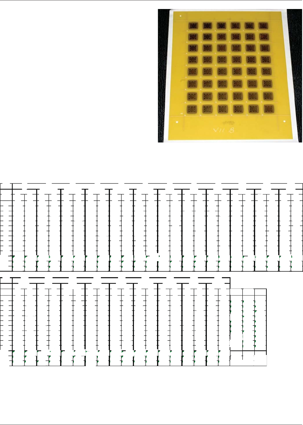
Figure A8-2 Example of 6 inx8inPanel Containing 1 in x
1in ENEPIG Wire Bond Coupons
Table A8-II Destructive Wire Bond Pull Test Force (grams) Results for All 21 ENEPIG Test Groups
IPC-4556 January 2013
60
ID
1A
1
2
3
4
5
6
7
8
9
10
Avg
Min
Max
X
1
I
Y
3
10.1
10.8
10.8
10.1
8.75
8.65
9.2
10.9
7.75
9.66
7.75
10.9
3
8.25
10.8
10.9
11.2
11.2
10.6
11.5
11.2
11.9
10.2
2
10.8
8.25
11.9
II-SN13-3
X Y
3
9.8
10.1
9.9
10.6
8.3
8.8
11.3
10.9
10.3
9.9
9.98
8.3
11.3
3
11
11.8
12
12.2
11.1
11.8
11.6
11.2
11.8
3
11.7
11
12.5
II-SN13-4
X Y
3
9.5
8.9
11
9.7
10.1
7.65
9.4
11.2
10.6
12.5
7.35
3
10.4
11.9
9.53
7.35
11.2
11.5
12
12.2
12.6
12.3
12.5
10.9
11.5
4
11.7
10.4
12.6
III SN7-2
X Y
3
9.75
9.55
9.05
9.65
9.7
10.9
9.5
9.65
9.75
9.9
3
10.6
11.1
11.1
11.3
11.5
9.74
9.05
10.9
10.9
11
11.2
11.5
11.9
5
11.2
10.6
11.9
II SN7-3
X Y
3
10.1
10.7
10.4
9.1
9.9
10.2
5.8
9.5
10.4
10.4
9.63
5.8
10.7
3
10.6
10.9
7.8
9.85
9.9
10.7
10.9
10.6
10.9
6
10.2
7.8
10.9
III SN7-4
X Y
3
9.6
9.4
10.3
10.1
9.75
8.85
9.4
7.9
8.8
3
9.42
7.9
10.3
10.7
9.05
9.15
10.9
10.1
11.4
9.35
10.5
9.2
10.1
8.85
8.85
11.4
7
IVB
X Y
3
8.85
8.95
7.25
8.2
8.25
7.45
8.1
8.75
8.25
8.5
3
10.7
10.3
10.7
7.25
8.95
11.5
10
10.8
10.9
11.1
11.2
8
10
11.5
IXB
X Y
3
9.75
3
10.4
10
9.2
9.95
10.4
10.8
9.65
10.3
10.2
9.55
9.8
10.9
9.95
11.3
8.25
12.1
8.25
8.7
11.7
11.3
8.25
10.2
9
9.2
12.1
XXB
X Y
3
9.4
3
10.5
9
10.3
9.6 10
9.75
9.35
8.85
9.05
9.55
9.85
10.4
10.2
10.5
10.5
9.75 9.7
8.2
10
9.7
8.2
9.75 10.8
X
VA
Y
3
9.6
9.9
9.6
9.45
8.65
8.8
8.95
9.1
10.5
10.8 9.05
9.9
8.26
10.8 9.42 10.7 9.25 10.3 9.36
3
10.3
10.4
11.3
10.3
11.4
11.2
11.1
11.6
11.9
8.65
10.5
11.2
11
11
10.3
11.9
VIIA
X
Y
3
9.75
9.3
3
11.8
10.6
9.9 11.1
10.7
10.3
11.610.5
8.85
10.4
12
11.1
9.7
10.9
11.8
11.5
10.1
8.85
11.1
9.85
12.1
11.3
9.85
12
12.1
VIIB
X Y
3
7.45
8.15
8.95
9.3
12
9.45
9.35
3
9.65
9.45
10.8
9.9
8.9
9.3
10.5
5.55
9.25
9.55
11.8
8.95
12.4
9.22
5.55
9.84
7.45
10.8
12.4
ID
1
2
3
4
5
6
7
8
9
10
Avg
Min
13
Max
VIIIA
X
Y
3
3
10.1 10.5
8.8
9.15
9.55
9.9
9.1
9.45
8.35
9.9
10.5
10.2
9
11.2
11.3
7.35
12
12.5
10.6
11.9
9.44
7.35
10.5
10.7
8.8
12.5
14
XB
X
Y
3
3
9.05
8.7
8.65
9.25
9.95
10.1
9.95
9.65
10.6
12.4
9.4
8.9
10.1
10.1
10
9.9
9.8
9.8
8.9
9.95
9.4
8.65
15
10.1
8.9
10 12.4
XIB
X Y
3
8.8
8.95
8.95
9.8
9.45
9.05
3
8
9.5
12.1
10.1
10.6
11.1
11.5
11.4
11.9
9.6
8.45
10.9
10.1
12.7
10.9
8
9.4
8.45
10.9 12.7
16
XIIA
X Y
3
9.8
9.3
10.2
9.6
10.1
3
10.2
10.2
10.4
10.3
10.3
10.3 10.3
8.95
10.2
9.5 10.2
10.2
9.85
10.5
10.2
9.8 10.2
10.2
8.95
10.5
17
10.4
XXIB
X
Y
3
3
9.85
9.25
7.3
8.5
9.75
9.9
11.3
10.4
10.2
8.95
10.4
9.9
9.85
10.3
10.1
10.1
9.7
10.5
10
9.35
9.84
8.95
18
9.7
7.3
10.5 11.3
XXII-2A
X
Y
3
3
9.559.4
10 8.35
10.6
7.25
9.15
8.45
8.75
10.2
8.4
8.85
8.7
9.25
10.2
9.9
9.95
10.1
10.1 10.4
9.05
7.25
9.69
8.35
10.2 10.6
19
XXIVA
X
Y
3
9.95
9.2
9.55
10.8
9.15
8.9
3
9.2
8.35
8.5
9.35
9.9
8.45
8.9
9.8
9.9
8.85
10.1
8.75
9.35
9.75
9.24
8.35
10.1
20
9.42
8.75
10.8
XXR
X
Y
3 3
8.95
10.6
9.05 9.15
9.55
10
9.4
10.3
10.7
10.1
10.3
7.5
8.8 8.8
10.6
7.75
9.95
8.7
8.910.2
9.42
7.5
10.6
9.49
21
7.75
10.7
XXVA
X
Y
3
3
9.1 9.9
10.2
10.8
9.45
11.8
10.6
11.5
10
10.2
10.3
10
10.2
10.5
9.55
10.1
10.2
10.1 10.2
9.99
9.1
10.5
10.6
9.45
11.8
AVG
9.57
9.69
9.84
10.01
9.96
9.80
9.99
7.45
8.15
7.25
8.2
8.25
7.45
10.24
5.8
10.14 5.55
11.6
10.17
7.75
7.35
9.57
Min
10.24| 8.25
Max
11.8
11.9
12
12.2
12.2
12.6
12.3
12.5
11.9
12.5
5.55
11.80]
12.55