IPC-4556 印制板化学镍钯浸金(ENEPIG)规范ENG.pdf - 第66页
Figure A7-16 SAC305 T est Coupon 19 – T est Coupon at 200X magnification (left view) and at 500X magnification (right view) and both are cross-sectional views. Discussion Figure A7-17 shows the solderball shear data as a f…
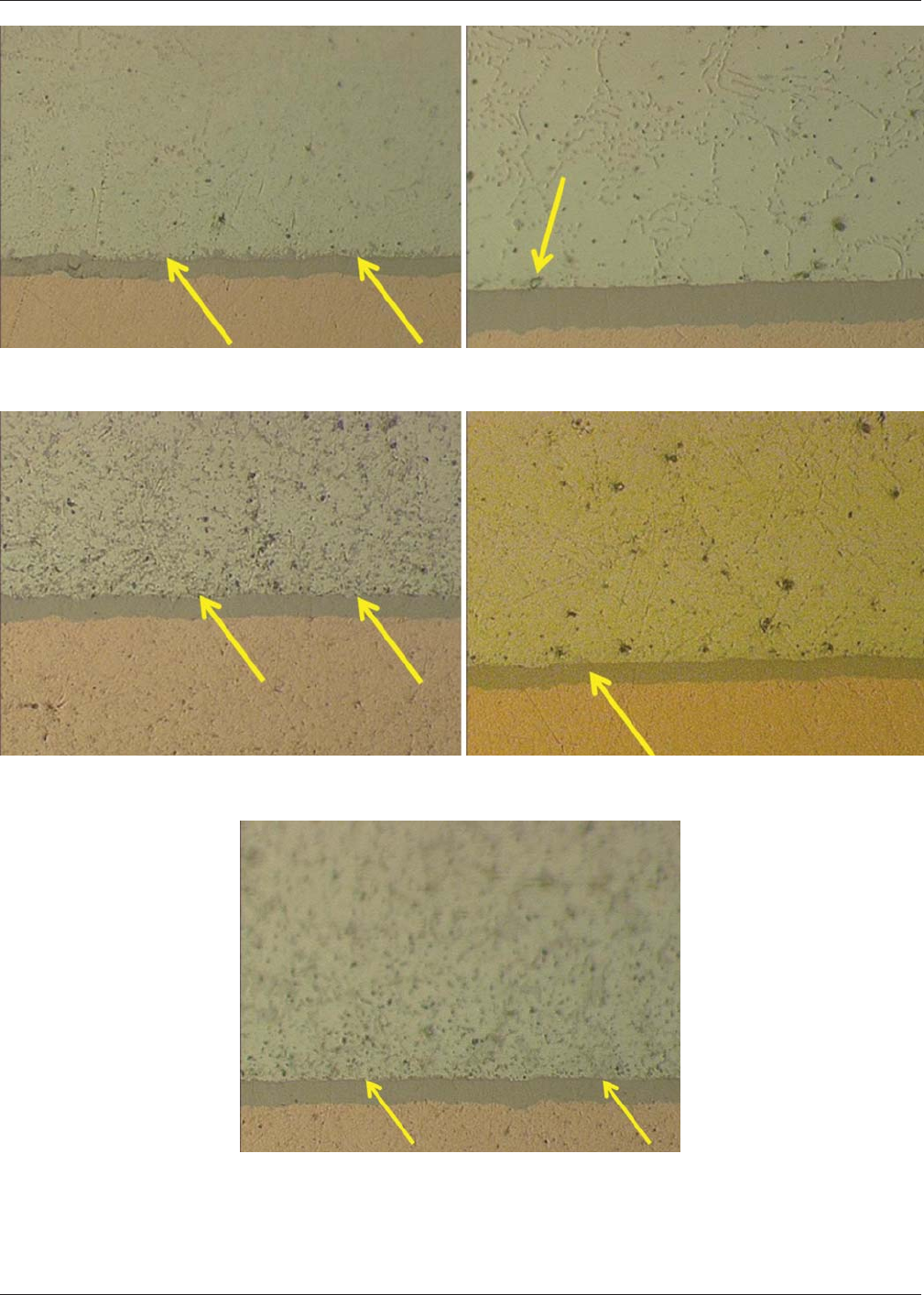
Figure A7-13 SAC305 Test Coupons5&6–Test Coupon 5 (left view) and Test Coupon 6 (right view) are both cross-sections at 500X
magnification.
Figure A7-14 SAC305 Test Coupons 16 & 17 – Test Coupon 16 (left view) and Test Coupon 17 (right view) are both cross-sections at
500X magnification.
Figure A7-15 SAC305 Test Coupon 18 – 500X magnification
cross-section view
January 2013 IPC-4556
55
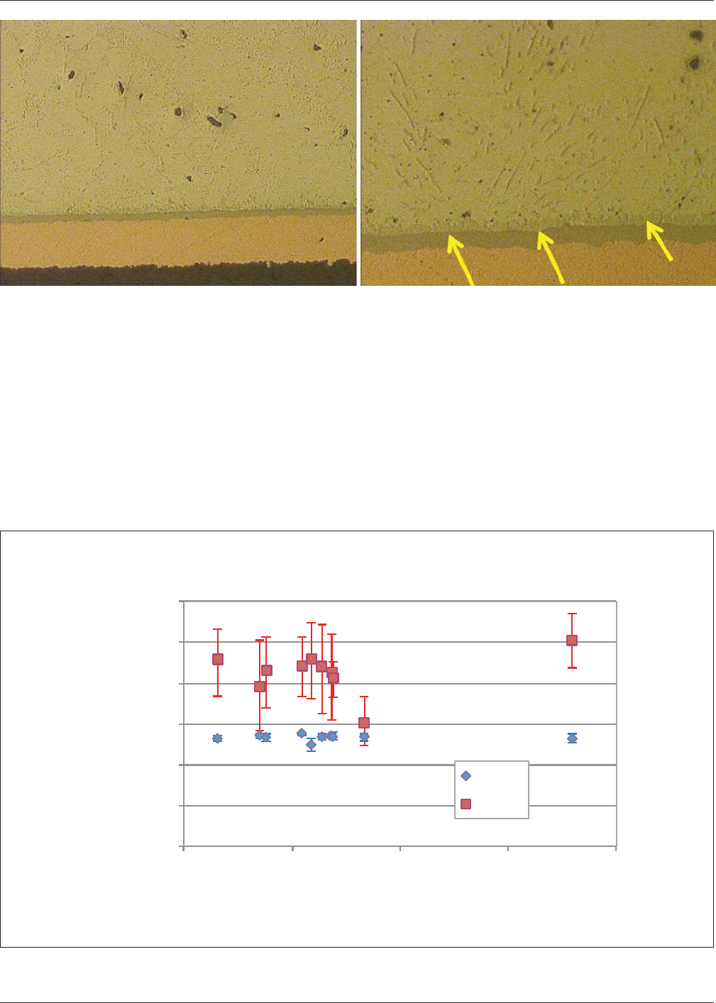
Figure A7-16 SAC305 Test Coupon 19 – Test Coupon at 200X magnification (left view) and at 500X magnification (right view) and both
are cross-sectional views.
Discussion Figure A7-17 shows the solderball shear data as a function of palladium plating thickness for both the
Sn63Pb37 and SAC305 soldering processes. The error bars in the plot represent one standard deviation. The Sn63Pb37 sol-
dering process shear force values are very consistent with little variation over the range of palladium plating thickness. The
SAC305 soldering process shear force values are more variable but greater than the Sn63Pb37 values. A solder joint integrity
issue due to PdSn
4
IMC phase embrittlement would have revealed itself as a loss of shear force with increasing palladium
plating thickness. The metallographic cross-sectional analysis confirms the Figure A7-17 data as the presence of the PdSn
4
IMC phase was not segregated at the solder joint/test coupon pad and was only found in minor concentration levels. The test
results recorded in this investigation are in agreement with recently published testing palladium plating reliability results by
M. Wolverton [2] and previous Rockwell Collins investigations [3].
IPC-4556-a7-17
Figure A7-17 Solderball Shear Force as a Function of Palladium Plating Thickness
3000
2500
2000
1500
1000
500
0 5 10 15 20
0
Solderball Shear on ENEPIG Surface Finish
Shear Force (g)
Palladium Plating Thickness (microinch)
SnPb
SAC305
IPC-4556 January 2013
56

CONCLUSION
The palladium plating thickness range on the test coupons submitted by the IPC 4-14 Plating Processes Subcommittee did
not introduce any loss of solder joint integrity for Sn63Pb37 or SAC305 soldering processes as measured by solderball shear
testing and metallographic cross-sectional analysis.
REFERENCES
1. D. Abbott, Donald, D. Romm, B. Lange, ‘‘Nickel-Palladium-Gold Integrated Circuit Lead Finish and Its Potential for
Solder-Joint Embrittlement,’’ Texas Instruments Application Report SZZA031, December 2001.
2. M. Wolverton, ‘‘Quality, Reliability and Metallurgy of ENEPIG Board Finish and Tin-Lead Solder Joints,’’ SMTAI Con-
ference Proceedings, October, 2011.
3. D. Hillman, P. Bratin, M. Pavlov, ‘‘Wirebondability and Solderability of Various Metallic Surface Finishes For Use in
Printed Circuit Assembly,’’ Surface Mount International Conference Proceedings, pp. 687-701, 1996.
January 2013 IPC-4556
57