IPC-4556 印制板化学镍钯浸金(ENEPIG)规范ENG.pdf - 第32页
SUMMARY • Based on the round robin testing, there should be concern regarding accuracy of ENEPIG measurements. If the protocols outlined in the XRF APPENDIX 4 are not followed, then some equipment will at best be a rando…

Results:
From the round robin testing, the following can be stated:
1) For Immersion Gold readings, the majority of the readings were on the high side with only one location reading the
thickness correctly. Two locations produced readings; one high and one low; that were so far out of the range as to be
meaningless.
2) For Electroless Palladium, four of the machines recorded readings that were correct with the majority of the other read-
ings being low. Again, one of the machines that produced meaningless gold readings also produced similar readings for
Palladium and maintained consistency regarding the error reading being low.
3) For the Electroless Nickel, there were eight participants that were within an acceptable range of the actual readings.
The remainder of the locations read the sample LOW.
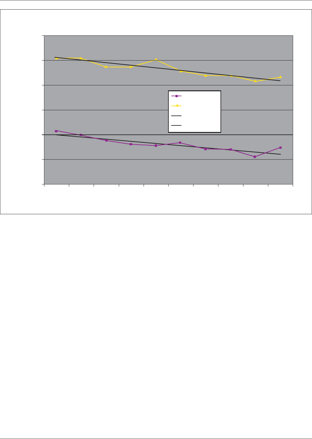
In addition to this testing, another series of XRF measurements were taken to evaluate the impact of feature size on the
deposit thickness plated at the same time on the same board. The board was again measured on the same reference XRF
unit. A summary of the results is shown in Figure A3-5.
Table A3-1 Comparison of the Accuracy of Measurements Relative to the C Readings for All Three Deposits
XRF machine Nickel Thickness Palladium Thickness Gold Thickness
A Low Low High
B Low High High
C Correct Correct Correct
D Low Correct High
E Correct Low High*
F Correct Low High
G Correct Low* Low*
H Correct Correct High
I Correct Correct High
J Low Low Low
K Correct Low Low
L Low Correct High
M Low High Correct
N Correct High* High
*Note: Readings were so far out as to be meaningless
January 2013 IPC-4556
21
SUMMARY
• Based on the round robin testing, there should be concern regarding accuracy of ENEPIG measurements. If the protocols
outlined in the XRF APPENDIX 4 are not followed, then some equipment will at best be a random number generator.
• It is imperative that Gauge Repeatability & Reproducibility protocols be run on all XRF equipment used in the supply
chain and comparison testing using traceable certified national standards to ensure accuracy of measurement and hence
performance of the ENEPIG deposit.
• Some equipment currently in use for other surface finishes will not meet the requirements for accuracy and repeatability
and will need to be replaced - this is the cost of supplying and using ENEPIG as a multifunctional surface finish.
• Feature size affects the deposit thickness for ENEPIG similar to other finishes. The use of the specified 60 mil X 60 mil
pads cannot be emphasized enough to minimize variation between measurements that will make meeting the proposed
specification limits nearly impossible.
• The XRF supplier base was absent from the study and their lack of participation in correctly setting up, evaluating equip-
ment and suggesting alternatives for older equipment is troubling, to say the least. Without their support, ENEPIG perfor-
mance will be open to criticism that is not warranted, due to incorrect thicknesses being supplied.
IPC-4556-A3-5
Figure A3-5 The Impact of Feature Size on Electroless Palladium and Immersion Gold Deposition Thickness Plated
on the Same PB
microinches
Au & Pd thickness as a function of pad area
380 380 452 452 612 612 1792 1792 50343 50343
area in mils square
y=-0.2012x+10.443
R
2
= 0.8099
y=-0.1752x+4.2373
R
2
= 0.7856
Au
Pd
Linear (Au)
Linear (Pd)
IPC-4556 January 2013
22

APPENDIX 4
Factors Affecting Measurement Accuracy
of ENEPIG Coatings by XRF
Frank Ferrandino, Technical Manager
Calmetrics Inc.
XRF has become ubiquitous in the plating industry for measuring plated layer thicknesses.
Among its many virtues, the XRF method tends to typically be robust for a wide range of plating applications. However,
the plating industry in response to increasing demand for reliability, continues to develop new coating combinations that can
make the analysis of thickness by XRF more complicated and therefore increasingly subject to error if not calibrated and
used properly. In particular, the use of ENEPIG coatings in the PCB industry, to improve shelf life and solderability, pres-
ent some challenges to the typical XRF instrument used to measure it.
Typical XRF Instruments Used for Plating Thickness Measurements A sizable majority of the XRF instruments used by
PCB manufacturers are good general purpose plating thickness testers equipped with either a tungsten (W) target or molyb-
denum (Mo) target x-ray source and gas filled proportional detectors. Such products are capable of achieving reasonably
good accuracy when measuring ENEPIG plating thicknesses. On the other hand, it is also easy for measurement accuracy to
be compromised when such XRF instruments do not have certain software functions or are not properly calibrated.
Below is a list of potential sources of errors when measuring ENEPIG coatings with proportional counter XRF systems using
W or Mo x-ray sources:
(1) The PCB epoxy laminate often contains fire retardant compounds of bromine.
The default measurement condition for these types of XRF instruments is to count the number of Au x-rays detected for
the Au L-β line (energy ~ 11.4 keV).
This is because the Au L-α peak overlaps the Cu x-ray peaks which originate from the Cu layer. In XRF analysis, we
try to avoid interferences caused by such overlaps when possible, hence the usual choice of analyzing the Au L-β line.
Normally when plating on Cu or Cu alloy substrates there is no interference with the Au L-β peak. However, in the
case of PCB samples, there is a reasonably good chance that some Br x-ray emission will be detected from the epoxy
substrate. Given the relatively poor energy resolution of proportional counter x-ray detectors, Br, with a K-α energy of
~ 11.9 keV will produce a spectral peak that overlaps or interferes with the usually reliable Au L-β peak. Normally, Br
x-ray intensity will be low since the Br x-rays must pass through the Cu, Ni, Pd, and Au layers to reach the detector
and be counted. These layers provide significant reduction in Br intensity due to shielding, resulting in only a small,
minor Br peak intensity.
In the case of immersion Au layers, which only produce a low intensity Au L-β peak, this small Br contribution to the
peak intensity of Au, if not corrected, can be significant since the Br contribution to the Au peak intensity is roughly
the same level of magnitude or even greater compared to the Au peak intensity itself.
When measuring immersion Au layers in the 0.05 µm - 0.13 µm [2 - 5 microinch] range uncorrected Br interference can
add anywhere from a few sub-microns or microinches for the gold measurements to as much as tenths of microns or
tens of microinches. Therefore, a Au layer which is truly 0.1 micron [4 microinches] for example, may measure any-
where from 0.15 µin to 0.25 µm [6 µin to 10 µin ] or more, if the Br interference is not accounted for and corrected.
The amount of error will depend primarily on the thickness of the Cu layer (thinner copper results in larger errors in
an Au measurement), the amount of Br compound in the epoxy and the spatial resolution of the x-ray beam and its
position relative to the plated areas being measured.
Fortunately, most if not all the XRF instruments used for plating thickness measurements offer peak deconvolution soft-
ware. This software will allow the instrument to breakdown the composite Au + Br peak into its component parts.
Therefore, it is possible to extract Au L-β peak intensity information independent of the contributing interference from
Br. For accurate measurement of immersion Au on PCB’s, use of a peak deconvolution routine is prudent and in many
cases absolutely vital to maximizing the accuracy of the Au thickness measurement. It should be noted that significant
errors in Au thickness measurement due to uncorrected Br interference will contribute to errors in the calculation of
underlying electroless Ni and Pd thicknesses, as well.
January 2013 IPC-4556
23