IPC-4556 印制板化学镍钯浸金(ENEPIG)规范ENG.pdf - 第73页
Upon completion of the final wire bonding and submission of data, the plating finish sample thicknesses were obtained and summarized. The results are shown in T able A8-III. SUMMARY The tasks identified through consensus of…
IPC-4556-a8-4
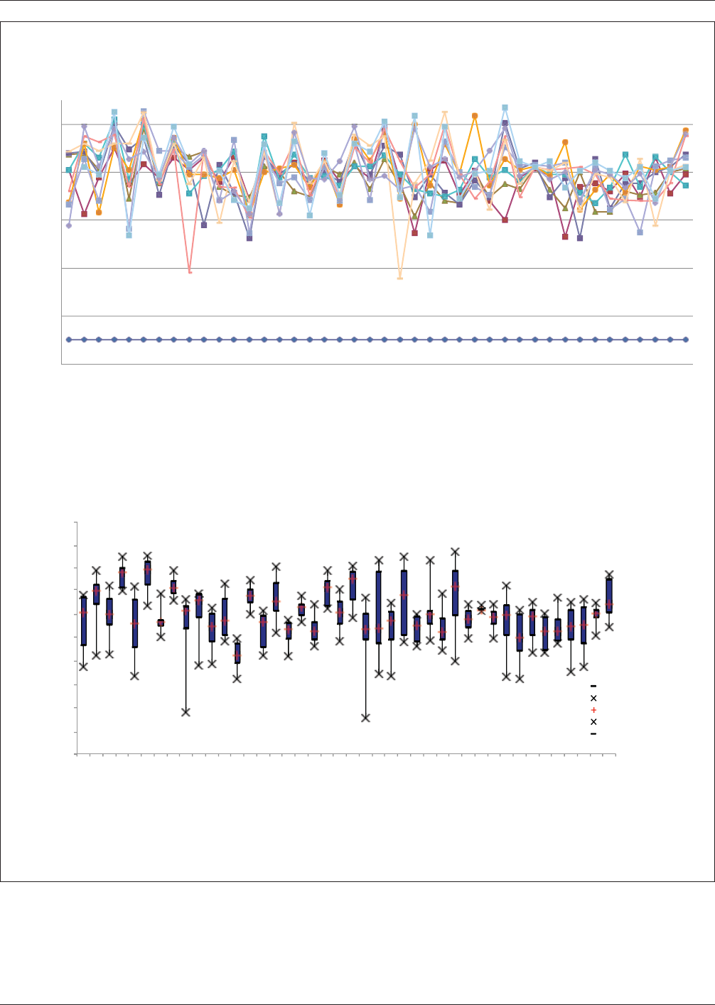
Figure A8-4 (Top) Summary of 1 mil Gold Wire ENEPIG Destructive Pull Test (DPT) Results and (Lower) Comparison of X-Y
Directional DPT Values
4
2
6
8
10
12
Destructive Pull Values (Grams)
Data S
Plating Methodology: Wilrebond Direction
et #1
Data Set #2
Data Set #3
Data Set #4
Data Set #5
Data Set #6
Data Set #7
Data Set #8
Data Set #9
Data Set #10
Data Set #11
Data Set #12
Data Set #13
Data Set #14
Data Set #15
Data Set #16
Data Set #17
Data Set #18
Data Set #19
Data Set #20
Data Set #21
Data Set #22
Data Set #23
Data Set #24
Data Set #25
Data Set #26
Data Set #27
Data Set #28
Data Set #29
Data Set #30
Data Set #31
Data Set #32
Data Set #33
Data Set #34
Data Set #35
Data Set #36
Data Set #37
Data Set #38
Data Set #39
Data S
et #40
Summary of NiPdAu Destructive Wire Bond Pull Tes
Data Set #41
Data Set #42
t for 1-MIL Gold Wire
I II-SN13-3 II-SN13-4 III-SN7-2 III-SN7-3 III-SN7-4
IVB IXB XXB
VA VIIA VIIIA XB
XIB
XIIA
XXIB XXII2-A XXIVA
Participants
Uyemura - Japan
Uyemura - US
XXR
XXVA
A
DOW
MacDermid
Cookson-Ethone
OMG
Atotech
Mil-STD 883 Requirement = 3 Grams
14
13
12
11
10
9
8
7
6
5
4
ENEPIG Plating Finish 1-mil Gold Wirebond Results X-Y Bond DPT Comparison
Q1
Min
Median
Max
Q3
IPC-4556 January 2013
62
Upon completion of the final wire bonding and submission of data, the plating finish sample thicknesses were obtained and
summarized. The results are shown in Table A8-III.
SUMMARY
The tasks identified through consensus of the IPC 4-14 Plating Processes Subcommittee to evaluate the suitability of Elec-
troless Nickel Electroless Palladium Immersion Gold (ENEPIG) as a finish for gold ball wire bond bondability included
development of an industry Round Robin with roles and responsibilities, development of a wire bond test vehicle, partici-
pation of commercial ENEPIG plating finish suppliers, establishment of ENEPIG plating finish attributes to evaluate the wire
bonding and 1 mil gold ball wire bonding destructive pull testing evaluation per MIL-STD883.
The wire bond test vehicle artwork was supplied by Kulicke and Soffa, fabrication of the test vehicle was conducted by TTM
Technologies, Inc. and the ENEPIG plating finish was supplied by commercial suppliers, Uyemura, Dow Electronic Mate-
rials, MacDermid, Enthone-Cookson, OMG and Atotech.
The electroless palladium target thicknesses were 4, 8, 12 and 20 microinches. The nickel and immersion gold thicknesses
were not considered variables.
One set of 1 mil gold ball wire bond parameters were selected for testing all six (6) ENEPIG supplier finishes evaluated in
this study.
All destructive pull testing results for all 6 commercial ENEPIG plating finish suppliers were in compliance with MIL-STD-
883 requirements.
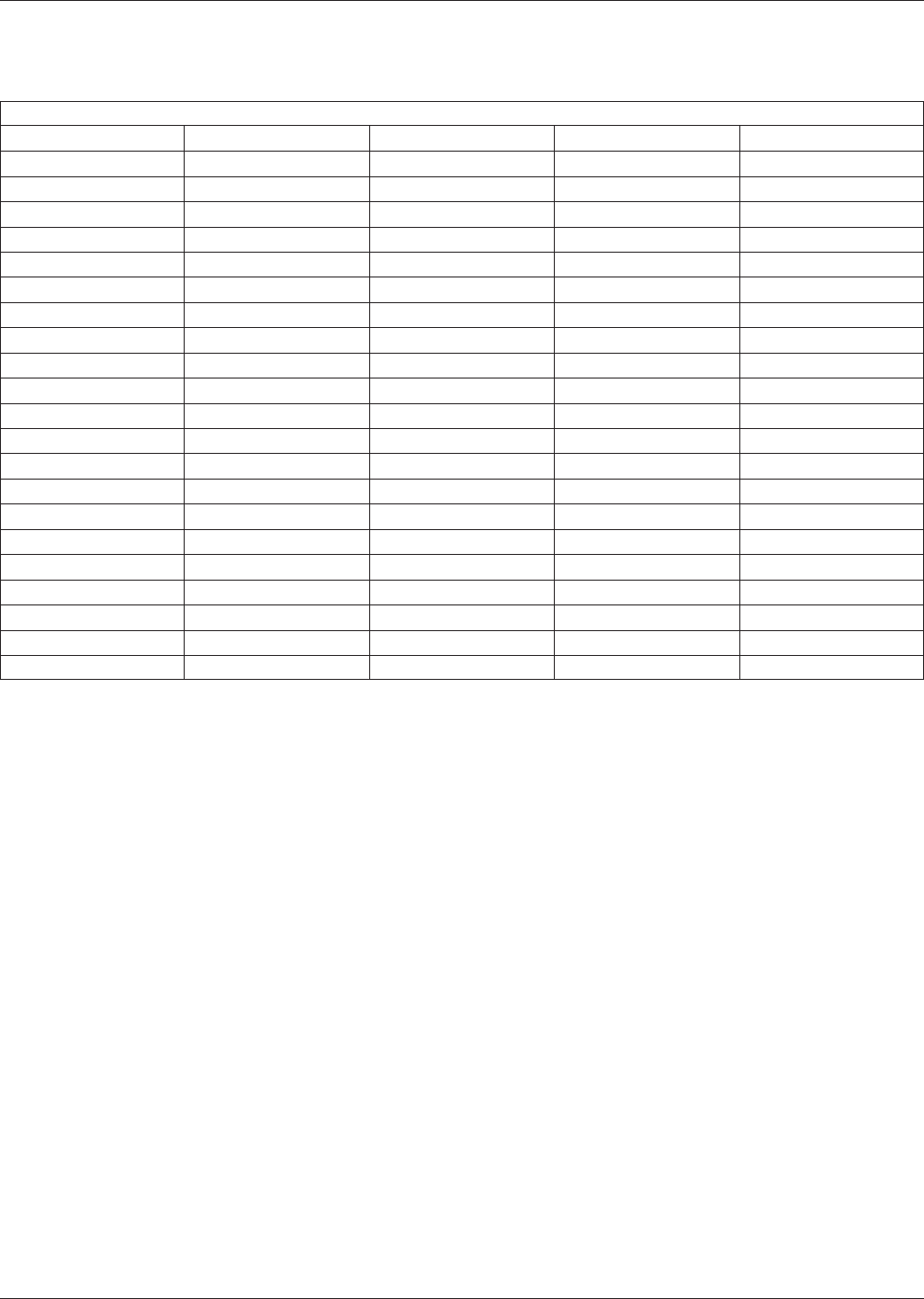
Table A8-III Summary of Plating Finish Thicknesses for Samples Wire Bonded
Summary of Plating Finish Thickness per Tracking Codes (µinches)
ID Code ID IAu Thickness (µin) EPd Thickness (µin) EN Thickness (µin)
1 I 2.07 3.48 349.32
2 II-SN13-3 2.2 5.49 343.83
3 II-SN13-4 2.54 6.84 371.24
4 III-SN7-2 2.9 1.57 190.3
5 III-SN7-3 2.15 6.38 175.14
6 III-SN7-4 3.3 8.32 182.84
7 IVB 1.64 5.78 176.75
8 IXB 0.77 9.95 190.16
9 XXB 0.72 16.26 176.21
10 VA 1.16 4.46 217.78
11 VIIA 1.82 7.76 212.54
12 VIIB 2.06 10.34 202.79
13 VIIIA 2.22 4.39 280.83
14 XB 1.42 7.48 267.04
15 XIB 1.68 11.01 254.14
16 XIIA 1.35 3.8 181.65
17 XXIB 1.24 5.93 184.07
18 XXII-2A 1.59 6.9 209.22
19 XXIVA 1.48 17.95 196.17
20 XXR 0.56 4.77 219.95
21 XXVA 0.73 7.37 236.76
January 2013 IPC-4556
63
APPENDIX 9
XRF Thickness Measurements of thin Au and Pd (ENEPIG):
Recommendations for Instrumentation (Detectors) and their Limitations
Michael Haller
Chief Operating Offıcer
Fischer Technology
• The given limitations in Table A9-1 for the minimal measurable thickness is based on measurements of a typical sample
with 50 nm Au and 100 nm Pd plated on 4 µm Ni, over 30 µm Cu on a substrate of fiberglass-reinforced epoxy resin with
Br for the given total intensities. Measuring time 120 s.
• Intensities are given for reference. If lower intensities are realized for a certain XRF setup appropriate adjustments should
be made, by either increasing collimator size (while still meeting spot size specifications) or by increasing the measure-
ment time.
• Detector limits are derived from repeatability precision (standard deviation) of the XRF instruments and based on count-
ing statistics which directly relate to total intensity and measurement time. As a general rule, in order to improve the repeat-
ability precision by a factor of 2 an increase in intensity or measurement time of a factor of 4 is required.
• The minimum measurable thickness for proportional counter detectors is limited due to the strong influence of the PCB
base material (Br) and Cu thicknesses (background signal and peak overlap).
• The use of calibration standards with similar thicknesses to the specified ENEPIG thicknesses which are to be measured
is recommended. Tri-layer standards where Au and Pd are plated directly on Ni/Cu/PCB should be used for calibration for
Cu thicknesses >30 µm. Tri-layer foil standards where Au and Pd are plated on a Ni-foil should be used if boards with
varying Cu-thickness are to be measured. The foils allow for great flexibility since they can be placed on various base
materials, therefore achieving optimal accuracy. With decreasing Cu thickness the influence of the PCB material becomes
more and more significant and requires careful calibration.
• For Cu thickness >30 µm a combination of a minimum of two calibration standards with approximate thicknesses as below
should be used.
– Au/Pd/Ni/Base 50 nm/20 nm/3 µ
– Au/Pd/Ni/Base 50 nm/90 nm/3 µ
– Au/Pd/Ni/Base 50 nm/300 nm/3 µ
– Au/Pd/Ni/Base 10 nm/20 nm/3 µ
• For Cu thicknesses <30 µm a combination of a minimum of two calibration foil standards with approximate thicknesses
as below should be used
– Au/Pd/Ni 60 nm/20 nm/4 µ
– Au/Pd/Ni 60 nm/60 nm/4 µ
– Au/Pd/Ni 50 nm/100 nm/4 µ
– Au/Pd/Ni 50 nm/250 nm/4 µ
• To verify accuracy, it is most important after the XRF has been calibrated for the appropriate measurement range, that the
instrument will read Au and Pd values of an uncoated board of the measurement sample as statistically zero. Only in this
way can one ensure that no systematic offset in the calibration and setup exists. (i.e., measure on uncoated Ni/Cu/PCB or
Cu/PCB and record Au and Pd values obtained).
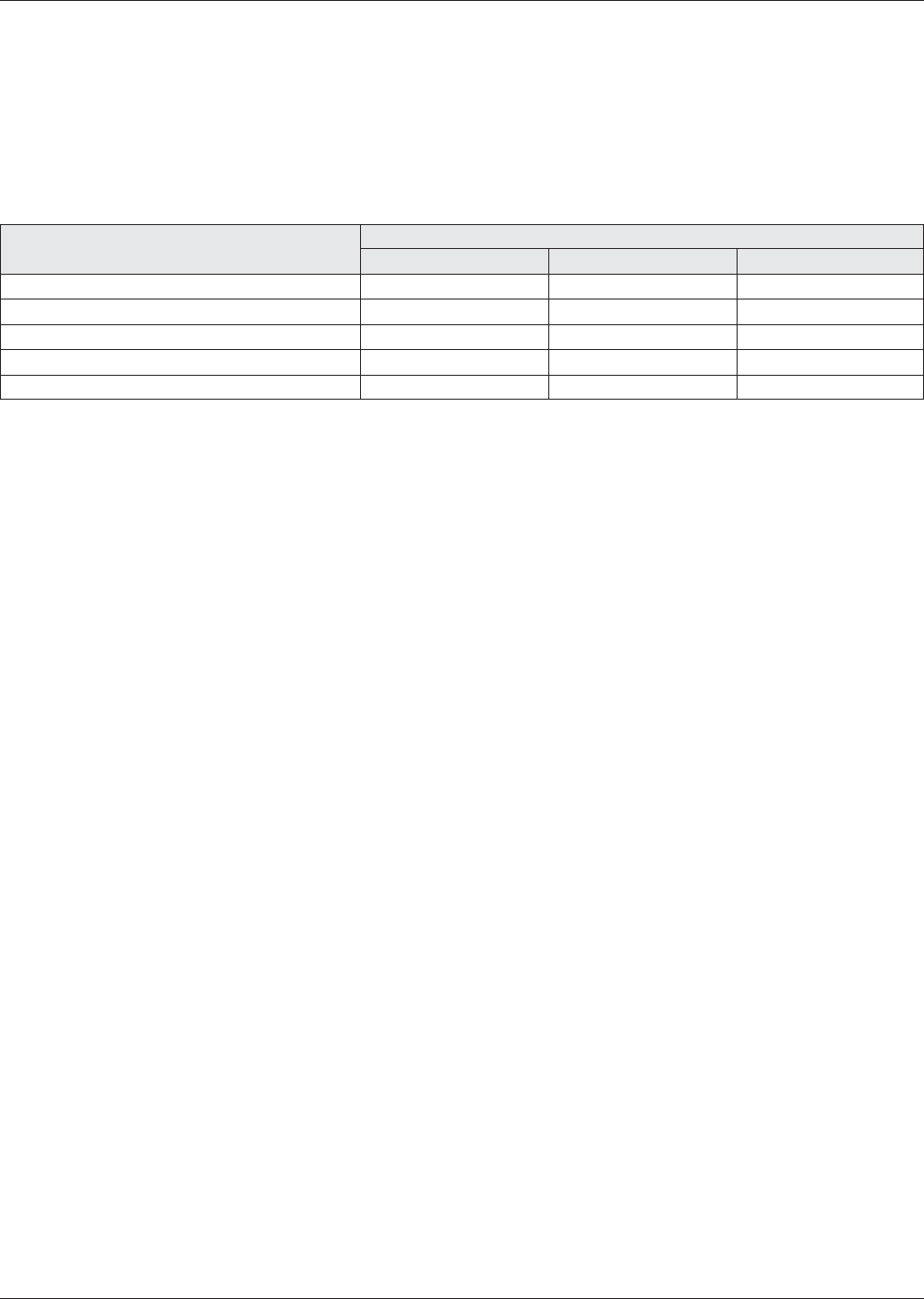
Table A9-1 XRF Detectors and Their Limitations at Typical Count Rates
Detector type
Prop. Counter PIN SDD
Au min ~ 70 - 100 nm ~ 5-10 nm ~ 2 nm
Pd min ~ 100 nm ~ 10 nm ~ 5 nm
Total Intensity 8000 cps 50 000 cps 50 000 cps
PCB and Cu Influence strong medium medium
Typical Energy Resolution for min Kα 900 eV <200 eV <150 eV
IPC-4556 January 2013
64