IPC-4556 印制板化学镍钯浸金(ENEPIG)规范ENG.pdf - 第58页
APPENDIX 7 ENEPIG PWB Surface Finish Shear Test Project Dave Hillman, Brad W illiams, T im Pearson, Ross W ilcoxon and Jennet V olden Rockwell Collins Inc. INTRODUCTION Rockwell Collins conducted solderball shear testing…

CONCLUSIONS
The solder spread on ENEPIG with the Sn/Pb/Ag solder paste (ROL1) was very high (good), regardless of ENEPIG chem-
istry, deposit layer thickness, or damp heat conditioning.
• The solder spread on ENEPIG with the Pb-free solder paste (ROL0) was lower than the Sn-Pb results.
• Damp heat conditioning prior to solder paste printing negatively impacted the spread for the Pb-free solder paste. The worst
samples exhibited localized areas of dewetting.
• No correlation (linear R
2
<0.1) was found between the solder spread and the electroless palladium layer thickness (range
tested: 0.05-0.45 µm) or IG layer thickness (range tested: 0.015-0.085 µm).
• Some correlation (linear R
2
~ 0.45) was observed between the Pb-free solder spread and the EN layer thickness (range
tested: 4.5-9.5 µm), with the thickest EN deposits having the highest spread and the lowest spread observed for low EN
thicknesses.
January 2013 IPC-4556
47
APPENDIX 7
ENEPIG PWB Surface Finish Shear Test Project
Dave Hillman, Brad Williams, Tim Pearson, Ross Wilcoxon and Jennet Volden
Rockwell Collins Inc.
INTRODUCTION
Rockwell Collins conducted solderball shear testing for the IPC 4-14 Plating Processes Subcommittee as part of their efforts
to create a specification for electroless nickel/electroless palladium/immersion gold (ENEPIG) circuit card finishes. A test
program was conducted to assess the solderball shear strength of a series of test coupons with different electroless palladium
plating thicknesses using both tin/lead and lead-free soldering processes.
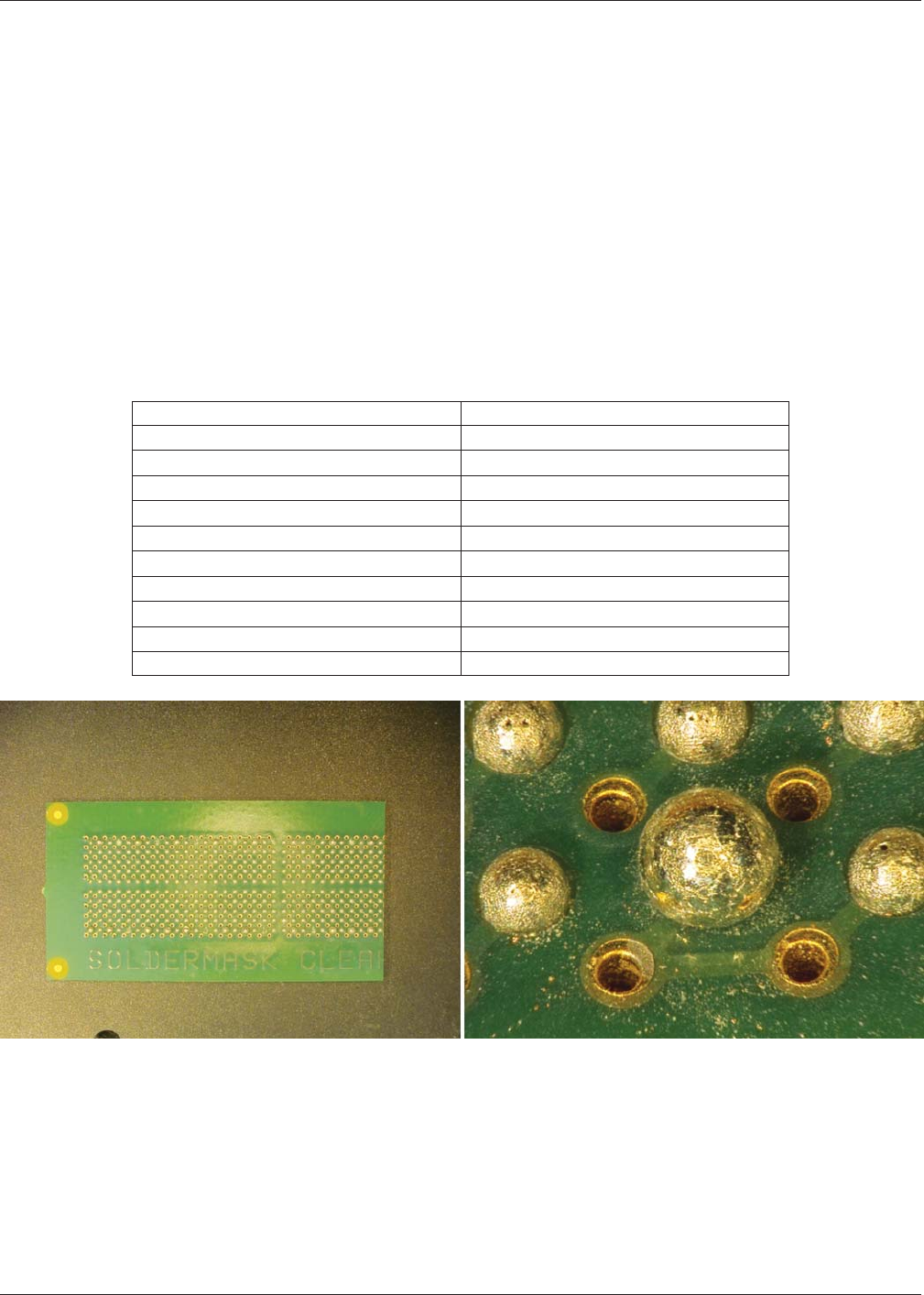
Test Vehicle The IPC 4-14 subcommittee supplied solderball shear test coupons that were 2.4 inches long x 0.93 inches
wide x 0.063 inches thick. The solderball pad was 0.025 inches in diameter. The palladium thickness varied for each coupon.
Table A7-1 lists the measured palladium thickness/coupon combinations and Figure A7-1 illustrates the shear test coupon.
Solder Processes The shear test coupons were manually stenciled using low residue tin/lead (Sn63Pb37) and lead-free
(SAC305) solder pastes per IPC-JSTD-004 and a 0.005 inch thick stainless steel stencil. A 0.025 inch diameter Sn63Pb37
alloy solder sphere and a 0.035 inch diameter SAC305 alloy solder sphere were manually placed on a random selection of
stenciled deposits. The test coupons were then processed in a five zone Electrovert Omniflow reflow oven using a nitrogen
reflow atmosphere. The peak reflow temperature for the Sn63Pb37 alloy was 220 °C and for the SAC305 alloy was 245 °C.
The Time Above Liquidus for the Sn63Pb37 alloy was 30-60 seconds and for the SAC305 alloy was 45-90 seconds. The test
coupons were cleaned using an in-line cleaner that used Kyzen Aquanox A4625 saponifier/deionized water solution.
Table A7-1 Test Coupon Serial Number and Palladium Thickness
Sample Number Pallidium Thickness (µinches)
1 3.48
2 5.49
3 6.84
4 1.57
5 6.38
6 8.32
16 3.8
17 5.93
18 6.9
19 17.95
Figure A7-1 Shear Test Coupon – Note right portion of the test coupon is missing due to removal for cross-sectional analysis (left view)
and close up view of solder paste deposit reflowed on coupon pads (smaller solder joints) and a pad with a solderball reflowed on pad (large sol-
der joint) (right view)
IPC-4556 January 2013
48
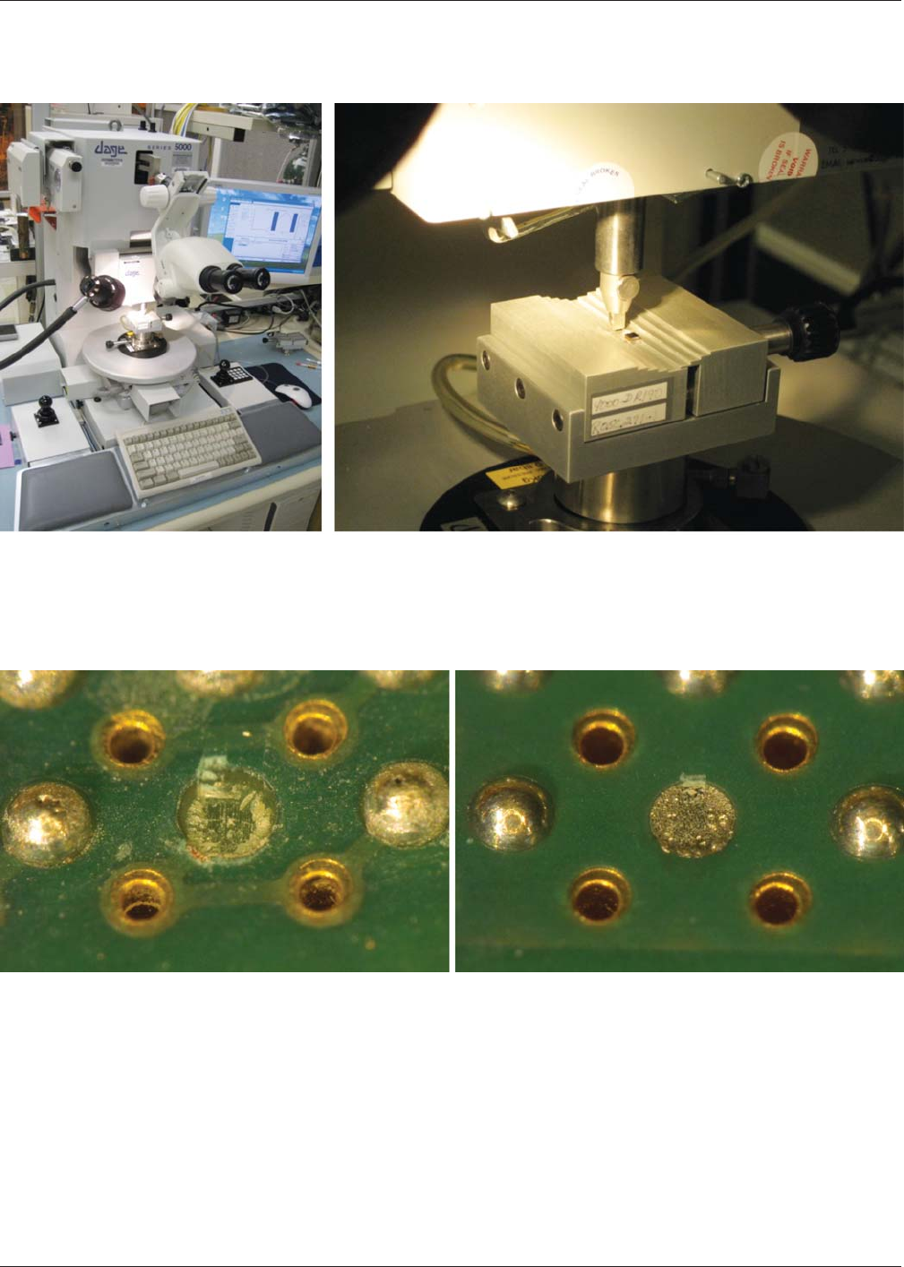
Shear Test Parameters The solderball shear testing was conducted using a DAGE 5000 shear test system. A BS5KG car-
tridge was used with a 50 gram ball shear load. A shear speed of 500 um/second, a shear height of 50 µm and an over travel
distance of 100 µm were used in the test. Figure A7-2 illustrates the DAGE 5000 shear system used in the test.
Figure A7-2 DAGE 5000 Shear Test System – Macro View (left view) and Close Up of Shear Head (right view)
All of the shear test failures were of a cohesive nature and not of an adhesive mode at the solder joint or coupon pad loca-
tions. The latter adhesive failure modes are illustrated in Figure A7-3.
Figure A7-3 Solderball Shear Results – Coupon pad ripped out of board during shear test (left view) and solderball sheared through sol-
der joint during shear test (right view)
January 2013 IPC-4556
49