IPC-4556 印制板化学镍钯浸金(ENEPIG)规范ENG.pdf - 第71页
1 mil Gold Wire Bonding and Destructive Pull Testing Evaluation per MIL-STD-883 The 1 mil gold wire bond parameters developed for the ENEPIG plating finish test vehicles were based upon the same 1 mil gold wire bond appro…
The samples in the package marked ‘‘Hand Cut’’ were not
evaluated.
The individual wire bond coupons were immediately labeled
with the same designation used for the panel prior to removal
of the coupon from the panel and packaging (Table A8-I and
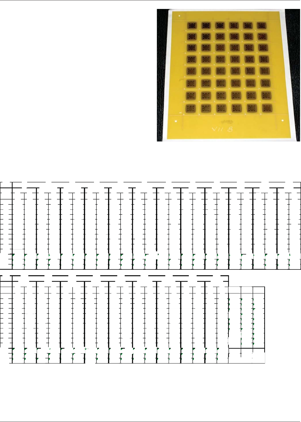
Figure A8-2). To ensure maximum traceability from coupon to
coupon and supplier to supplier, a standard label approach was
adopted for wire bonding to each test vehicle.
The identical wire bond locations on each coupon were used
for wire bonding for each of the 6 different ENEPIG suppliers
followed by destructive pull testing. For example, wire bond
pad location #1 in the X-direction per Figure A8-1 was the
same location used for all 21 panel groups. Wire bond loca-
tion #2 corresponded to location number 2 for all 21 panel
groups. Panel groups were composed of six (6) Suppliers, four
(4) different palladium thicknesses and two (2) levels of sur-
face roughness (Table A8-II).
Figure A8-2 Example of 6 inx8inPanel Containing 1 in x
1in ENEPIG Wire Bond Coupons
Table A8-II Destructive Wire Bond Pull Test Force (grams) Results for All 21 ENEPIG Test Groups
IPC-4556 January 2013
60
ID
1A
1
2
3
4
5
6
7
8
9
10
Avg
Min
Max
X
1
I
Y
3
10.1
10.8
10.8
10.1
8.75
8.65
9.2
10.9
7.75
9.66
7.75
10.9
3
8.25
10.8
10.9
11.2
11.2
10.6
11.5
11.2
11.9
10.2
2
10.8
8.25
11.9
II-SN13-3
X Y
3
9.8
10.1
9.9
10.6
8.3
8.8
11.3
10.9
10.3
9.9
9.98
8.3
11.3
3
11
11.8
12
12.2
11.1
11.8
11.6
11.2
11.8
3
11.7
11
12.5
II-SN13-4
X Y
3
9.5
8.9
11
9.7
10.1
7.65
9.4
11.2
10.6
12.5
7.35
3
10.4
11.9
9.53
7.35
11.2
11.5
12
12.2
12.6
12.3
12.5
10.9
11.5
4
11.7
10.4
12.6
III SN7-2
X Y
3
9.75
9.55
9.05
9.65
9.7
10.9
9.5
9.65
9.75
9.9
3
10.6
11.1
11.1
11.3
11.5
9.74
9.05
10.9
10.9
11
11.2
11.5
11.9
5
11.2
10.6
11.9
II SN7-3
X Y
3
10.1
10.7
10.4
9.1
9.9
10.2
5.8
9.5
10.4
10.4
9.63
5.8
10.7
3
10.6
10.9
7.8
9.85
9.9
10.7
10.9
10.6
10.9
6
10.2
7.8
10.9
III SN7-4
X Y
3
9.6
9.4
10.3
10.1
9.75
8.85
9.4
7.9
8.8
3
9.42
7.9
10.3
10.7
9.05
9.15
10.9
10.1
11.4
9.35
10.5
9.2
10.1
8.85
8.85
11.4
7
IVB
X Y
3
8.85
8.95
7.25
8.2
8.25
7.45
8.1
8.75
8.25
8.5
3
10.7
10.3
10.7
7.25
8.95
11.5
10
10.8
10.9
11.1
11.2
8
10
11.5
IXB
X Y
3
9.75
3
10.4
10
9.2
9.95
10.4
10.8
9.65
10.3
10.2
9.55
9.8
10.9
9.95
11.3
8.25
12.1
8.25
8.7
11.7
11.3
8.25
10.2
9
9.2
12.1
XXB
X Y
3
9.4
3
10.5
9
10.3
9.6 10
9.75
9.35
8.85
9.05
9.55
9.85
10.4
10.2
10.5
10.5
9.75 9.7
8.2
10
9.7
8.2
9.75 10.8
X
VA
Y
3
9.6
9.9
9.6
9.45
8.65
8.8
8.95
9.1
10.5
10.8 9.05
9.9
8.26
10.8 9.42 10.7 9.25 10.3 9.36
3
10.3
10.4
11.3
10.3
11.4
11.2
11.1
11.6
11.9
8.65
10.5
11.2
11
11
10.3
11.9
VIIA
X
Y
3
9.75
9.3
3
11.8
10.6
9.9 11.1
10.7
10.3
11.610.5
8.85
10.4
12
11.1
9.7
10.9
11.8
11.5
10.1
8.85
11.1
9.85
12.1
11.3
9.85
12
12.1
VIIB
X Y
3
7.45
8.15
8.95
9.3
12
9.45
9.35
3
9.65
9.45
10.8
9.9
8.9
9.3
10.5
5.55
9.25
9.55
11.8
8.95
12.4
9.22
5.55
9.84
7.45
10.8
12.4
ID
1
2
3
4
5
6
7
8
9
10
Avg
Min
13
Max
VIIIA
X
Y
3
3
10.1 10.5
8.8
9.15
9.55
9.9
9.1
9.45
8.35
9.9
10.5
10.2
9
11.2
11.3
7.35
12
12.5
10.6
11.9
9.44
7.35
10.5
10.7
8.8
12.5
14
XB
X
Y
3
3
9.05
8.7
8.65
9.25
9.95
10.1
9.95
9.65
10.6
12.4
9.4
8.9
10.1
10.1
10
9.9
9.8
9.8
8.9
9.95
9.4
8.65
15
10.1
8.9
10 12.4
XIB
X Y
3
8.8
8.95
8.95
9.8
9.45
9.05
3
8
9.5
12.1
10.1
10.6
11.1
11.5
11.4
11.9
9.6
8.45
10.9
10.1
12.7
10.9
8
9.4
8.45
10.9 12.7
16
XIIA
X Y
3
9.8
9.3
10.2
9.6
10.1
3
10.2
10.2
10.4
10.3
10.3
10.3 10.3
8.95
10.2
9.5 10.2
10.2
9.85
10.5
10.2
9.8 10.2
10.2
8.95
10.5
17
10.4
XXIB
X
Y
3
3
9.85
9.25
7.3
8.5
9.75
9.9
11.3
10.4
10.2
8.95
10.4
9.9
9.85
10.3
10.1
10.1
9.7
10.5
10
9.35
9.84
8.95
18
9.7
7.3
10.5 11.3
XXII-2A
X
Y
3
3
9.559.4
10 8.35
10.6
7.25
9.15
8.45
8.75
10.2
8.4
8.85
8.7
9.25
10.2
9.9
9.95
10.1
10.1 10.4
9.05
7.25
9.69
8.35
10.2 10.6
19
XXIVA
X
Y
3
9.95
9.2
9.55
10.8
9.15
8.9
3
9.2
8.35
8.5
9.35
9.9
8.45
8.9
9.8
9.9
8.85
10.1
8.75
9.35
9.75
9.24
8.35
10.1
20
9.42
8.75
10.8
XXR
X
Y
3 3
8.95
10.6
9.05 9.15
9.55
10
9.4
10.3
10.7
10.1
10.3
7.5
8.8 8.8
10.6
7.75
9.95
8.7
8.910.2
9.42
7.5
10.6
9.49
21
7.75
10.7
XXVA
X
Y
3
3
9.1 9.9
10.2
10.8
9.45
11.8
10.6
11.5
10
10.2
10.3
10
10.2
10.5
9.55
10.1
10.2
10.1 10.2
9.99
9.1
10.5
10.6
9.45
11.8
AVG
9.57
9.69
9.84
10.01
9.96
9.80
9.99
7.45
8.15
7.25
8.2
8.25
7.45
10.24
5.8
10.14 5.55
11.6
10.17
7.75
7.35
9.57
Min
10.24| 8.25
Max
11.8
11.9
12
12.2
12.2
12.6
12.3
12.5
11.9
12.5
5.55
11.80]
12.55
1 mil Gold Wire Bonding and Destructive Pull Testing Evaluation per MIL-STD-883 The 1 mil gold wire bond parameters
developed for the ENEPIG plating finish test vehicles were based upon the same 1 mil gold wire bond approach used in the
development of the wire bond parameters designed for production level substrates with gold plating finish.
Manufacturing processes and operations are inherently specific. While automatic wire bonders are similar, they may be dif-
ferent in specific aspects. Wire bond fixtures and capillaries are critical and play a significant role in a successful wire bond-
ing operation. The experience levels of the wire bond operator are also important.
Following removal of the coupons from the panel and marking of the coupons, the parts were baked in a nitrogen oven at
150 °C [302 °F] for 4 hours. The parts were then plasma cleaned and wire bonded. 120 wires were placed onto each con-
ditioned coupon. A minimum of 10 each 1 mil gold wires per coupon in the X-direction and 10 wires in the Y-direction were
bonded, followed by DPT (see Figure A8-1).
The 1 mil gold wire bonding parameters selected for bonding on substrates with an electrolytic gold plating finish were
modified for the bonding of ENEPIG coupons with the immersion gold finish, as follows:
Reduction in Power by 7%
Force was increased by 10%
Time was increased by 100%
Stage temperature at the substrate surface was 150 °C±5°C[302 °F ± 9 °F].
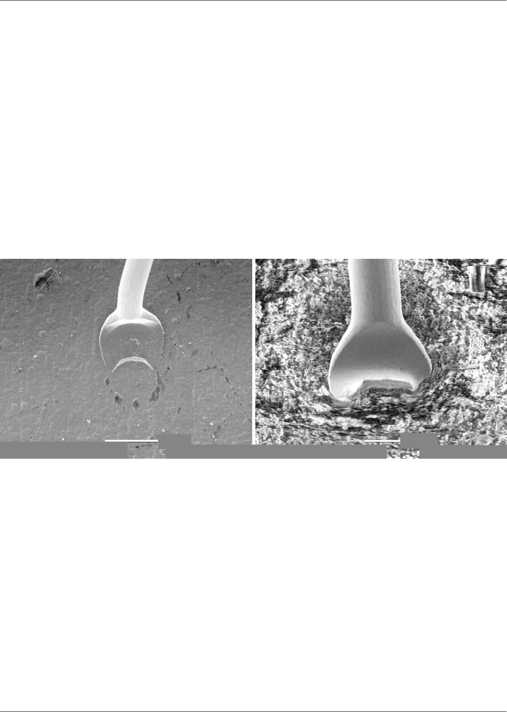
MIL-STD 883 destructive pull test requirements for all ENEPIG test vehicles were met (see Figures A8-3 and A8-4).
Figure A8-3 Visual Evaluation of Wire Bonding Showing Classical Crescents Resulting in Neck Breaks
(Left) Destructive Pull Test value of 12.5 grams / (Right) DPT is 5.5 grams
January 2013 IPC-4556
61
Vac-High PC-Std. 10 kV
50 m
4/5/2011 *000055 VarcHigh Pc Srd.oky
20 pm
41520412000056
IPC-4556-a8-4
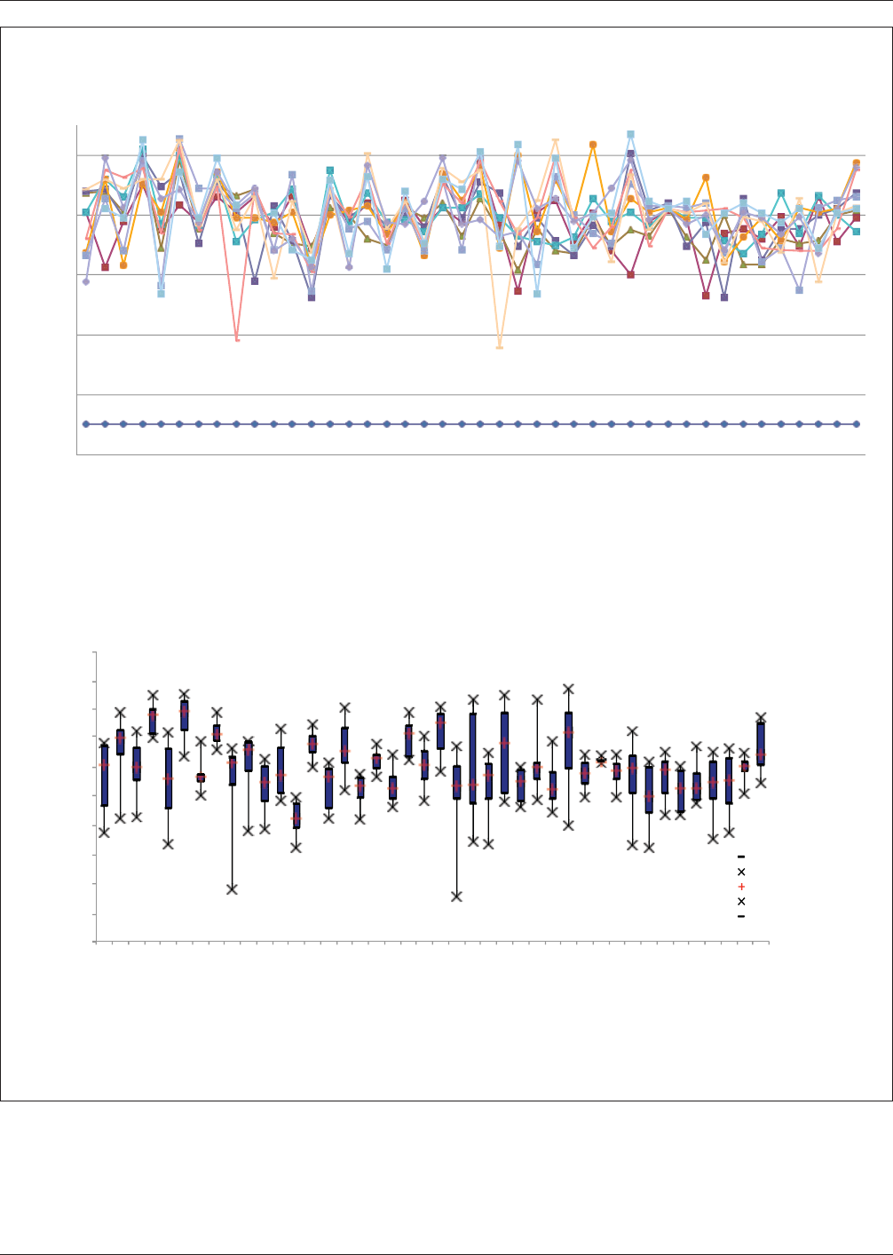
Figure A8-4 (Top) Summary of 1 mil Gold Wire ENEPIG Destructive Pull Test (DPT) Results and (Lower) Comparison of X-Y
Directional DPT Values
4
2
6
8
10
12
Destructive Pull Values (Grams)
Data S
Plating Methodology: Wilrebond Direction
et #1
Data Set #2
Data Set #3
Data Set #4
Data Set #5
Data Set #6
Data Set #7
Data Set #8
Data Set #9
Data Set #10
Data Set #11
Data Set #12
Data Set #13
Data Set #14
Data Set #15
Data Set #16
Data Set #17
Data Set #18
Data Set #19
Data Set #20
Data Set #21
Data Set #22
Data Set #23
Data Set #24
Data Set #25
Data Set #26
Data Set #27
Data Set #28
Data Set #29
Data Set #30
Data Set #31
Data Set #32
Data Set #33
Data Set #34
Data Set #35
Data Set #36
Data Set #37
Data Set #38
Data Set #39
Data S
et #40
Summary of NiPdAu Destructive Wire Bond Pull Tes
Data Set #41
Data Set #42
t for 1-MIL Gold Wire
I II-SN13-3 II-SN13-4 III-SN7-2 III-SN7-3 III-SN7-4
IVB IXB XXB
VA VIIA VIIIA XB
XIB
XIIA
XXIB XXII2-A XXIVA
Participants
Uyemura - Japan
Uyemura - US
XXR
XXVA
A
DOW
MacDermid
Cookson-Ethone
OMG
Atotech
Mil-STD 883 Requirement = 3 Grams
14
13
12
11
10
9
8
7
6
5
4
ENEPIG Plating Finish 1-mil Gold Wirebond Results X-Y Bond DPT Comparison
Q1
Min
Median
Max
Q3
IPC-4556 January 2013
62