00197501-02_AI_WPC_Umbau_X-Series_S_DE_EN.pdf - 第48页
Review 5 Anhang 5.2 Stromlaufpläne 48 Assembly Instructions / Montageanleitung SIPLACE WPC an SIPLACE X-Serie S SIPLACE WPC on SIPLACE X Se- ries S 03/2020 5.2.1 Aufrüstsatz WPC M2 CAN-Switch X-Serie S Abb.58: Aufrüstsa…
Review
5 Anhang
5.2 Stromlaufpläne
Assembly Instructions / Montageanleitung SIPLACE WPC an SIPLACE X-Serie S SIPLACE WPC on SIPLACE X Se-
ries S 03/2020
47
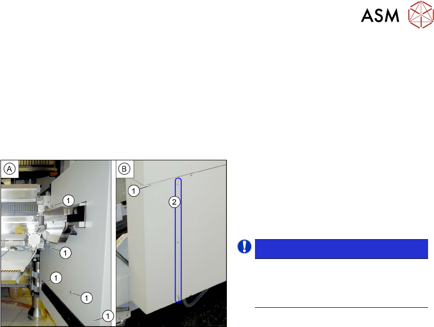
5.1.4 Untere Seitenverkleidung demontieren
Für viele Arbeiten ist es notwendig die untere Seitenverkleidung am Stellplatz zu demontieren.
Nachfolgend wird dies am Beispiel von Stellplatz 2 gezeigt. Die Vorgehensweise an anderen Stell-
plätzen ist analog.
Teile, Hilfsmittel und Werkzeug
●
Ggf. gekürzter Inbusschlüssel
Seitenverkleidung demontieren
Abb.57: Untere Seitenverkleidung demontieren
► Halten Sie die Seitenverkleidung wäh-
rend des Abschraubens fest, so dass
diese nicht herunterfallen kann.
► Entfernen Sie die sechs Befestigungs-
schrauben(1)
an der Innen-(A) und
Außenseite(B)
der Seitenverkleidung.
HINWEIS!
Die drei Befestigungsschrauben(2) an
der Außenseite sind standardmäßig
gelockert. Die Seitenverkleidung kann
hier herausgezogen werden.
.
► Nehmen Sie die Seitenverkleidung ab.
Seitenverkleidung montieren
► Die Montage erfolgt in umgekehrter Reihenfolge.
5.2 Stromlaufpläne
Weitere Informationen finden Sie in der Wirkschaltplanmappe:
●
Wirkschaltplanmappe SIPLACE X-Serie S (bis Gxxxx) [DEEN:00197021‑xx]
●
Wirkschaltplanmappe SIPLACE X-Serie S (ab Hxxxx) [DEEN:00197920‑xx]
Review
5 Anhang
5.2 Stromlaufpläne
48 Assembly Instructions / Montageanleitung SIPLACE WPC an SIPLACE X-Serie S SIPLACE WPC on SIPLACE X Se-
ries S 03/2020
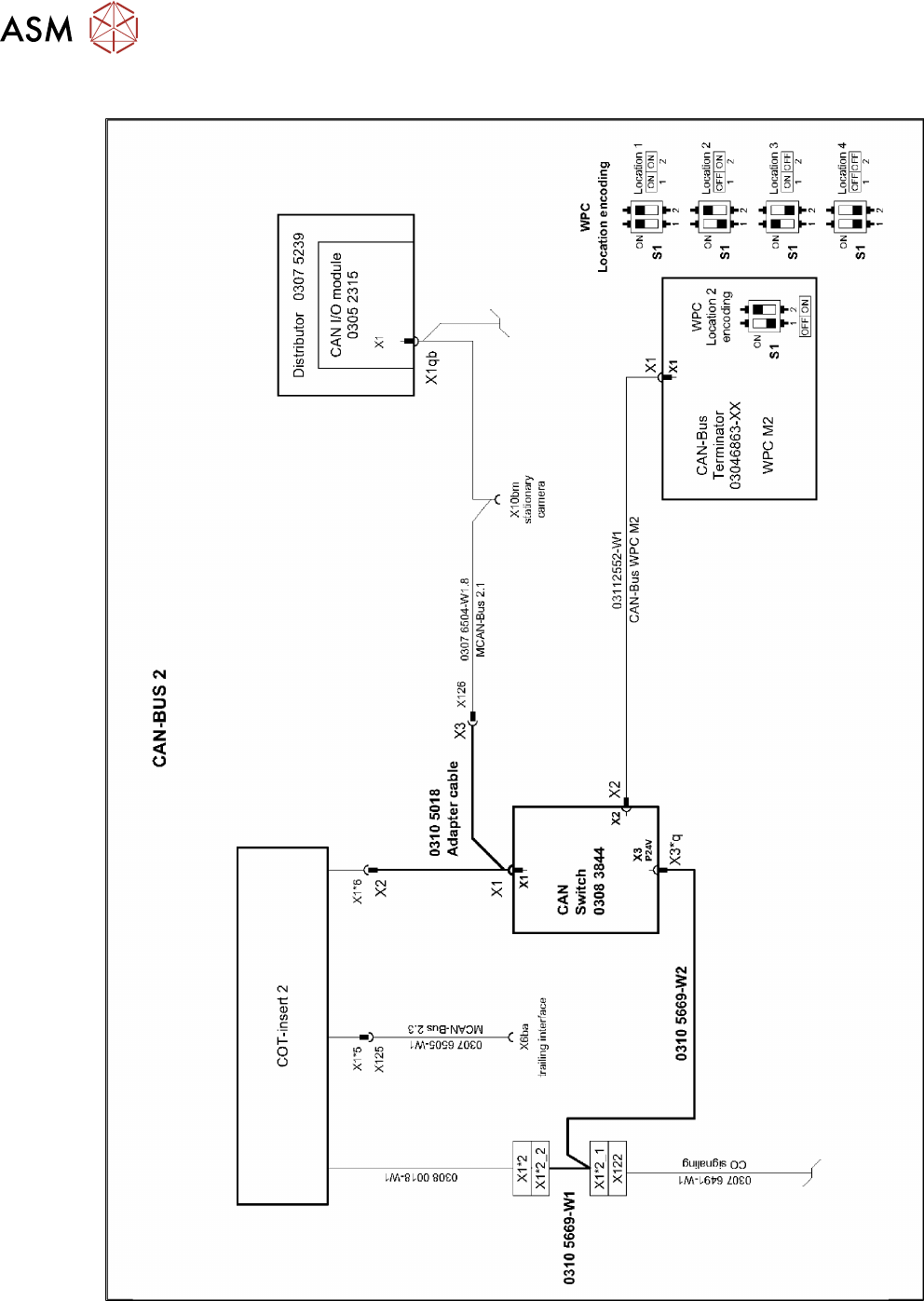
5.2.1 Aufrüstsatz WPC M2 CAN-Switch X-Serie S
Abb.58: Aufrüstsatz WPC M2 CAN-Switch X-Serie S

Review
49Assembly Instructions / Montageanleitung SIPLACE WPC an SIPLACE X-Serie S SIPLACE WPC on SIPLACE X
Series S 03/2020
Table of Contents
Table of Contents
1 Introduction.. 51
1.1 Safety instructions.. 51
1.1.1 Conventions for the use of safety instructions and symbols.. 51
1.1.2 Safety instructions for working with strong magnetic fields.. 52
1.1.3 Safety instructions for the power supply (without SMPS).. 52
1.1.4 Safety instructions for the power supply (with SMPS).. 53
1.1.5 Safety instructions for the compressed air supply.. 55
1.1.6 Safety instructions for work on the cutting device.. 55
1.1.7 Safety instructions for the gantry.. 55
1.1.8 Safety instructions on hazardous materials.. 55
1.2 Preparatory work..... 56
1.3 Other instructions.. 59
1.3.1 Environmentally-friendly disposal of materials and components.. 59
1.3.2 Use of original accessories and spare parts.. 59
1.3.3 ESD guidelines.. 59
1.3.3.1 What does ESD mean?.. 59
1.3.3.2 Important measures to protect against static charging.. 59
1.3.3.3 Handling ESD modules.. 60
1.3.3.4 Measurements and modifications to ESD modules.. 60
1.3.3.5 Dispatching ESD modules.. 60
1.3.4 Validity of Document.. 60
1.3.5 Release History.. 61
1.4 Abbreviations.. 61
2 Brief description.. 63
2.1 Overview of SIPLACE WPC5/WPC6.. 63
2.1.1 Overview of the Modules.. 64
2.2 Overview of SIPLACE WPC5/WPC6 insert.. 64
2.3 Scope of Delivery.. 65
2.4 Tools and Equipment Required.. 66
3 Setting up and Commissioning.. 67
3.1 Removing the Standard Component Trolley Feed Device.. 68
3.2 Installing the Manual Table.. 70
3.3 Fitting the CAN Switch.. 72
3.4 Fitting the bridge cover SIPLACE WPC on the SIPLACE X-Series S.. 76
3.5 Fitting the Waste Tape Slide.. 77
3.6 Adjusting the Hood.. 79
4 Operator Tasks.. 81
4.1 Docking the SIPLACE WPC5/WPC6.. 81
4.2 Undocking the SIPLACE WPC5/WPC6.. 83
4.3 Automatic Calibration.. 84