00197501-02_AI_WPC_Umbau_X-Series_S_DE_EN.pdf - 第80页
Review 3 Setting up and Commissioning 3.6 Adjusting the Hood 80 Assembly Instructions / Montageanleitung SIPLACE WPC an SIPLACE X-Serie S SIPLACE WPC on SIPLACE X Series S 03/2020 Fig.36: Track ruler The track scale mus…
Review
3 Setting up and Commissioning
3.6 Adjusting the Hood
Assembly Instructions / Montageanleitung SIPLACE WPC an SIPLACE X-Serie S SIPLACE WPC on SIPLACE X
Series S 03/2020
79
3.6 Adjusting the Hood
Before the SIPLACE WPC5/WPC6 can be moved to position 2, you need to replace the original
protective cover at the relevant location with the protective sheet assembly.
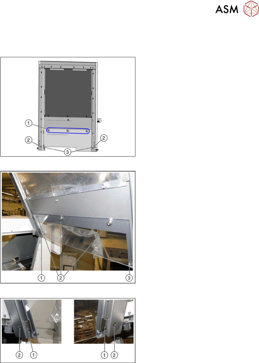
Fig.33: Hood with original protective cover at table position 1
There are three bolts on the inside of the
cover (1)
, where the protective cover is
hooked up and fixed.
► Remove the three hexagonal nuts that
fix the protective cover and lift off the
original cover.
► At (2), remove the fixture plate on both
sides (3)
.
Fig.34: Fixture points for protective plate
► Hook the protective plate onto the three
bolts and fasten these into place with
the three washers and the hexagonal
nuts (2)
that you previously removed.
► Also secure the protective plate with
the fixture plates on the left (1)
and
right (3)
.
Fig.35: Screwing the fixture sheets into place
► Insert the fixture sheets on the left and
right (1).
► Screw the fixture plates (2) into place
with the screws that you previously
removed.
Review
3 Setting up and Commissioning
3.6 Adjusting the Hood
80 Assembly Instructions / Montageanleitung SIPLACE WPC an SIPLACE X-Serie S SIPLACE WPC on SIPLACE X
Series S 03/2020
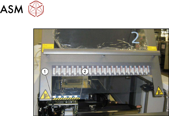
Fig.36: Track ruler
The track scale must have a distance of 5
mm to the metal edge (1)
.
► Use adhesive to fix the track ruler at all
locations towards the machine center (2)
.
Review
4 Operator Tasks
4.1 Docking the SIPLACE WPC5/WPC6
Assembly Instructions / Montageanleitung SIPLACE WPC an SIPLACE X-Serie S SIPLACE WPC on SIPLACE X
Series S 03/2020
81
4 Operator Tasks
4.1 Docking the SIPLACE WPC5/WPC6
When installing and removing the SIPLACE WPC5/WPC6, make sure that the arms of the feed
axis do not hit any parts (e.g. stationary cameras etc.).
► If the SIPLACE WPC5/WPC6 is not yet standing on its wheels, fasten the hexagonal shaft (crank
handle) to the lifting mechanism and turn in a clockwise direction, to lift the WPC5/WPC6.
► Stop turning when you have enough room to dock the SIPLACE WPC5/WPC6 onto the machine.
► Open the machine cover on the relevant location.
► If there is a height limiter present in the SIPLACE WPC5/WPC6 location, this needs to be
turned over and fixed into place upside down. Make sure that the height limiter does not touch
the cover plate. To do this, remove the three screws fastening the height limiter and fit it into
the same place upside down (with two fastening screws).
► Move the SIPLACE WPC5/WPC6 into the location and connect the energy and data supply
cable. Make sure that the arms of the feed axis do not collide with any machine parts.
► Connect the SIPLACE WPC5/WPC6 safety chain to the machine.
► Lower the SIPLACE WPC5/WPC6 until it is standing on its feet. Turn the crank handle on the
lifting mechanism until the wheels are about 1 cm above the ground.
Aligning the SIPLACE WPC5/WPC6
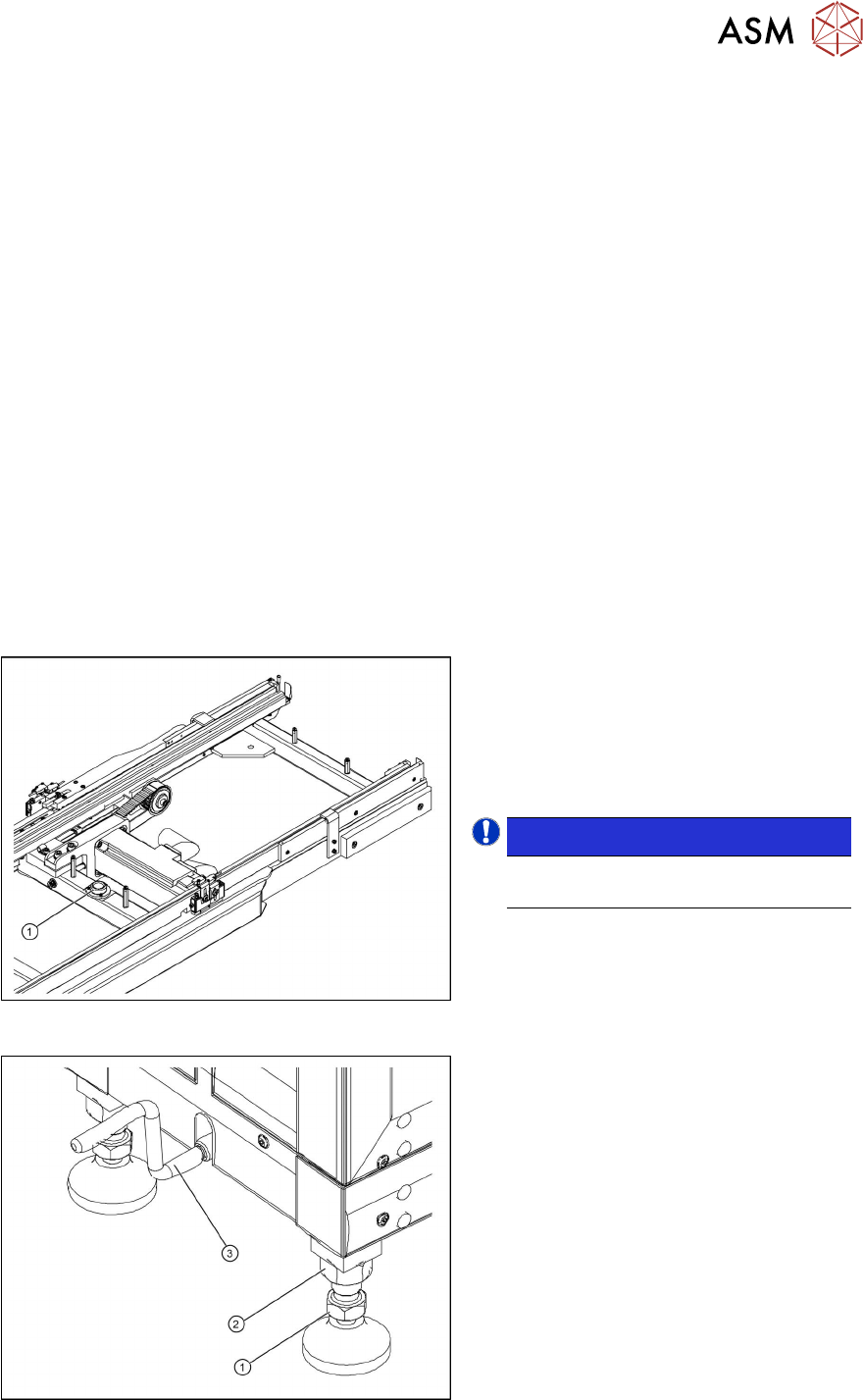
Fig.37: Circular spirit level
1. Circular spirit level
► Check the position of the SIPLACE
WPC5/WPC6 with the help of the integ-
rated spirit level (1)
, which is between
the two rails of the feeder axis.
NOTICE!
The cover on the feed axis arms is not
shown in the diagram.
.
Fig.38: Setting the adjustable feet
1. Foot with 30 mm nut
2. 36 mm locknut
3. Hexagonal shaft (crank handle)
► If the SIPLACE WPC5/WPC6 is not
level, use a 30 mm and 36 mm open-
ended wrench to adjust the feet in turn,
until more than half of the bubble is in
the circle of the spirit level.