00197501-02_AI_WPC_Umbau_X-Series_S_DE_EN.pdf - 第67页
Review 3 Setting up and Commissioning Assembly Instructions / Montageanleitung SIPLACE WPC an SIPLACE X-Serie S SIPLACE WPC on SIPLACE X Series S 03/2020 67 3 Setting up and Commissioning When operating the SIPLACE WPC…

Review
2 Brief description
2.4 Tools and Equipment Required
66 Assembly Instructions / Montageanleitung SIPLACE WPC an SIPLACE X-Serie S SIPLACE WPC on SIPLACE X
Series S 03/2020
Quantity Designation Item number
1 Nozzle changer TH SX-Series (position 1) 00519845-xx
1 Magazine holder cpl. / NC P+P B series 03062453-xx
3 Magazine assembly / 2 nozzles P+P 03005191-xx
1 Magazine assembly / 1 nozzle P+ 03001807-xx
1 Basic assembly NC row 2/W5 magazine: 03089888-xx
Upgrade kit for movable door SP2/4
Quantity Designation Item number
1 Upgrade kit for movable door SP2/4 03149589-xx
1 Hinge top assy SP 2/4 03098942-xx
1 Hinge bottom part assy 03098912-xx
1 Slider assy SX4a 03098934-xx
1 Handle assy. X-Series S SP2/4 03112952-xx
2 Hexagonal nut with clamping part and flange (re-
places DIN 6926)
03010699-xx
2 ISO 4762 - M 5 x 16-A2-70 03042562-xx
2 DIN EN ISO 4762 cylinder screw with hex. socket. 03042551-xx
1 DIN EN ISO 10511 HEXAGONAL NUT 03054130-xx
1 Serrated lock washer 03047857-xx
1 Contact washer 03047654-xx
1 Contact disc -6-FSt-flZnnc-480h 03047656-xx
2 ISO 7089 - 4 - 200 HV - A2 03100634-xx
1 EMC tape b=5mm KR M5 - KR M4 l=110mm 03103976-xx
1 Safety switch service flap 03090999-xx
1 Support safety switch window SX4a assy. 03093353-xx
3 Shim for service flap 03154631-xx
4 ISO 7089 - 4 - 200 HV - A2 03100634-xx
4 DIN EN ISO 10511 - M4-A2-70 03054130-xx
1 Actuating bracket B1-2053 for AZ15/16 00321649-xx
2 DIN 7991-TX m.Pin-M5 x 10-A2-70 03083825-xx
1 Ball holder 2053 f. AZ15/16 00321650-xx
2 ISO 4762 - M 5 x 16-A2-70 03042562-xx
2 ISO 7089 - 5 - 200 HV - A2 03100635-xx
2.4 Tools and Equipment Required
●
Standard tooling
●
Allen key set
●
Detailed circuit diagrams folder for SIPLACE X-Series S (up to Gxxxx) [DE+EN:00197021‑xx]
●
Detailed circuit diagrams folder for SIPLACE X-Series S (from Hxxxx) [DE+EN:00197920‑xx]
●
Mounting tool [03015976-xx]
●
Suitable lifting device (e.g. hand-operated crane)

Review
3 Setting up and Commissioning
Assembly Instructions / Montageanleitung SIPLACE WPC an SIPLACE X-Serie S SIPLACE WPC on SIPLACE X
Series S 03/2020
67
3 Setting up and Commissioning
When operating the SIPLACE WPC5/WPC6 on an SIPLACE X-Series S, you need to fit a fixed
table.
► First remove the standard COT insert (COTi-40). Then fit the fixed table with SIPLACE WPC
[03110607- xx] for the SIPLACE WPC5/WPC6.
► If not already present, fit a service flap. For details, read the assembly instructions for the
"Service flap X-Series S" [00197396-xx].
► See also the assembly instructions "SIPLACE X‑SeriesS input/output conveyor extension and
hand guard" [00197089‑xx]
► For conversion of the waste slide, refer to the chapter 3.5 "Fitting the Waste Tape
Slide" [}77].
► When operating the SIPLACE WPC5/WPC6 on the SIPLACE X-Series S, you also need to fit
a hand guard on the SIPLACE WPC. See also the chapter 3.4
"Fitting the bridge cover
SIPLACE WPC on the SIPLACE X-Series S" [}76].
► If an MTC2 was already fitted to the machine, you will also need to replace the slanted cover
guide with a straight one. See also the assembly instructions "SIPLACE X-Series S MTC2 on
location 2" [00197082-xx].
Review
3 Setting up and Commissioning
3.1 Removing the Standard Component Trolley Feed Device
68 Assembly Instructions / Montageanleitung SIPLACE WPC an SIPLACE X-Serie S SIPLACE WPC on SIPLACE X
Series S 03/2020
3.1 Removing the Standard Component Trolley Feed Device
WARNING
Risk of injury when working near the tape cutter.
When working in the area of the tape cutter, move the component trolley out of the machine
and disconnect the machine from the mains supply and the compressed air supply.
► Wait until the operating pressure has dropped to 0 MPa.
► Always secure the machine against unauthorized reactivation.
► Do not reach into the tape cutter.
CAUTION
Risk of injury when performing service work on the tape cutter.
Never support the tape cutter on your body, e.g., on your knees or thighs. Do not place
your feet under the tape cutter.
► Wear appropriately thick protective gloves.
► When removing/fitting the tape cutter, hold it only outside on the left and right.
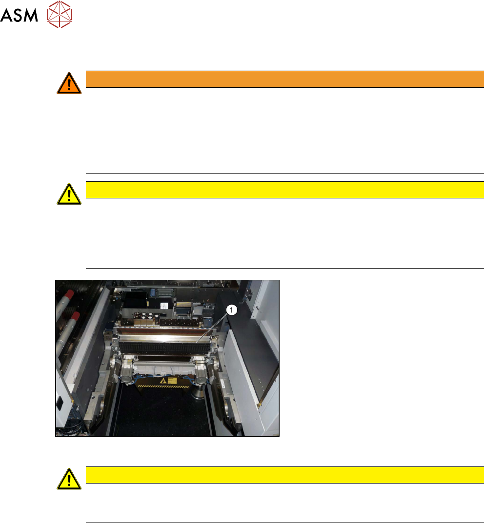
Fig.11: COT insert
1. COT insert
CAUTION
Heavy machine part!
The COT insert is heavy. To lift it out, you will need to use the mounting tool and a suitable
lifting device (hand-operated crane etc.).
Removal
► Switch off the machine, disconnect it from the power supply and secure it to prevent
unauthorized reactivation. See also section 1.2
"Preparatory work..." [}56].
► Dismantle the nozzle changer.
► Disconnect the COT insert from all electrical and pneumatic connections. Mark the positions
of these connections, to make clear assignment easier later on. The connection cables and
hoses are located behind the COT insert – in the space leading to the machine base (under
the nozzle changer). See also the chapter 5.1.3
"Nozzle Changers and Nozzle Stations -
Overview" [}89].
► Dismantle the left side cover. See also the chapter 5.1.4 "Dismantling the Lower Side
Cover" [}91].
► Unhook the middle cover.