00197501-02_AI_WPC_Umbau_X-Series_S_DE_EN.pdf - 第71页
Review 3 Setting up and Commissioning 3.2 Installing the Manual Table Assembly Instructions / Montageanleitung SIPLACE WPC an SIPLACE X-Serie S SIPLACE WPC on SIPLACE X Series S 03/2020 71 Fig.16: Heavy table for SIPLAC…
Review
3 Setting up and Commissioning
3.2 Installing the Manual Table
70 Assembly Instructions / Montageanleitung SIPLACE WPC an SIPLACE X-Serie S SIPLACE WPC on SIPLACE X
Series S 03/2020
3.2 Installing the Manual Table
NOTICE
Cables and hoses
► Before installing the table ensure to route all cables and hoses for the subsequent
connection.
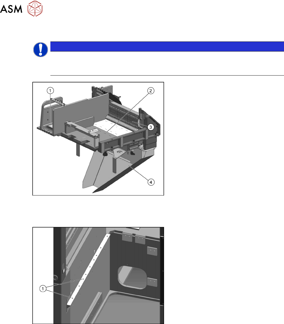
Fig.14: Manual table
1. Free tracks for tape reel container
assembly /WPC [03060460-xx]
2. Insertion for the SIPLACE WPC5/
WPC6
3. FCU
4. Waste slide, welded WPC / JTF
[03111440-xx]
► Before installing the fixed table, the waste slide must be removed. See also the chapter 3.5
"Fitting the Waste Tape Slide" [}77].
Fig.15: Installation position 3
The fixed table for the SIPLACE WPC5/
WPC6 is fitted to the outermost position of
the SIPLACE X-Series S.
1. Installation position 3
Review
3 Setting up and Commissioning
3.2 Installing the Manual Table
Assembly Instructions / Montageanleitung SIPLACE WPC an SIPLACE X-Serie S SIPLACE WPC on SIPLACE X
Series S 03/2020
71
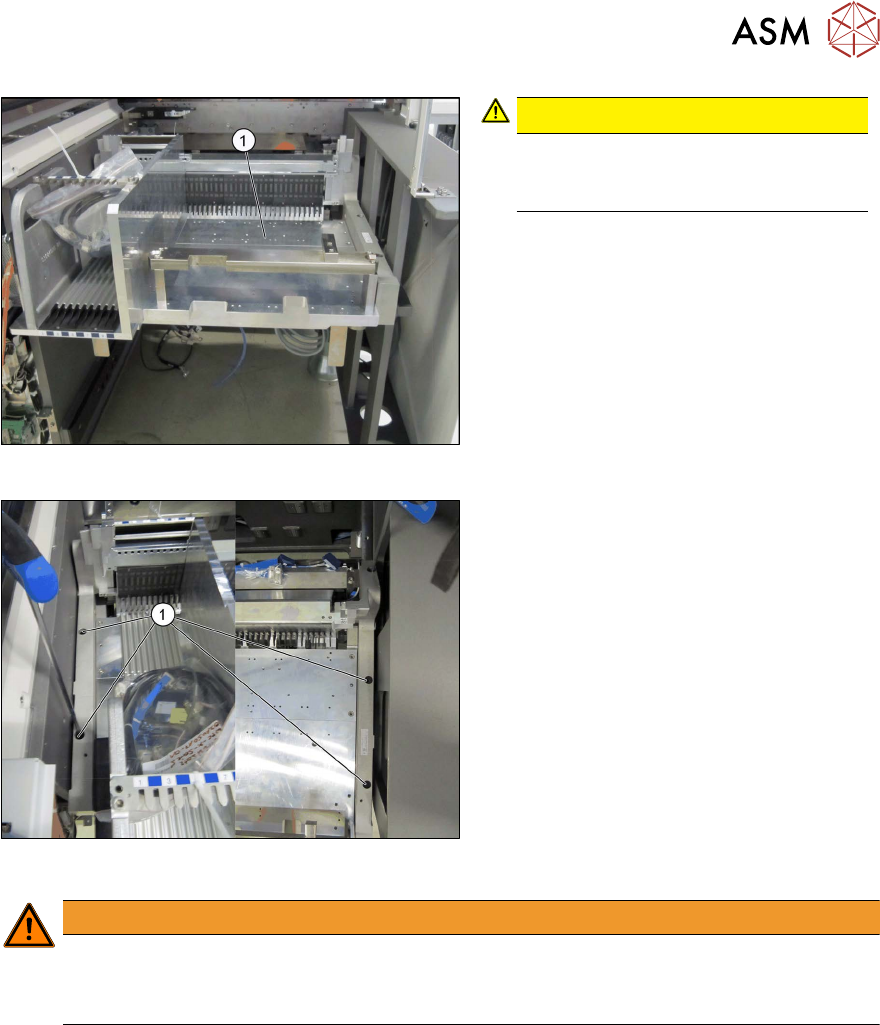
Fig.16: Heavy table for SIPLACE WPC5/WPC6
CAUTION!
Heavy machine part!
You might need to enlist the help of a
second person to prevent this.
.
► Lift the fixed table for the SIPLACE
WPC5/WPC6 (1)
into place.
► Pull the table forwards to position 3.
Fig.17: Fixing the fixed table into place
► Fix the fixed table for the SIPLACE
WPC5/WPC6 into place at position 3 in
the machine (1)
, with four screws
M8x20 [03042575-xx].
WARNING
Unstable frame
Dismantling the front section of the manual table can make the frame unstable.
► Do not dismantle the front section of the manual table.
Review
3 Setting up and Commissioning
3.3 Fitting the CAN Switch
72 Assembly Instructions / Montageanleitung SIPLACE WPC an SIPLACE X-Serie S SIPLACE WPC on SIPLACE X
Series S 03/2020
3.3 Fitting the CAN Switch
The CAN switch must be fitted for operating the SIPLACE WPC5/WPC6.
See also the attached information in the 5.2.1 "Upgrade kit WPC M2 CAN switch X-Series
S" [}92].
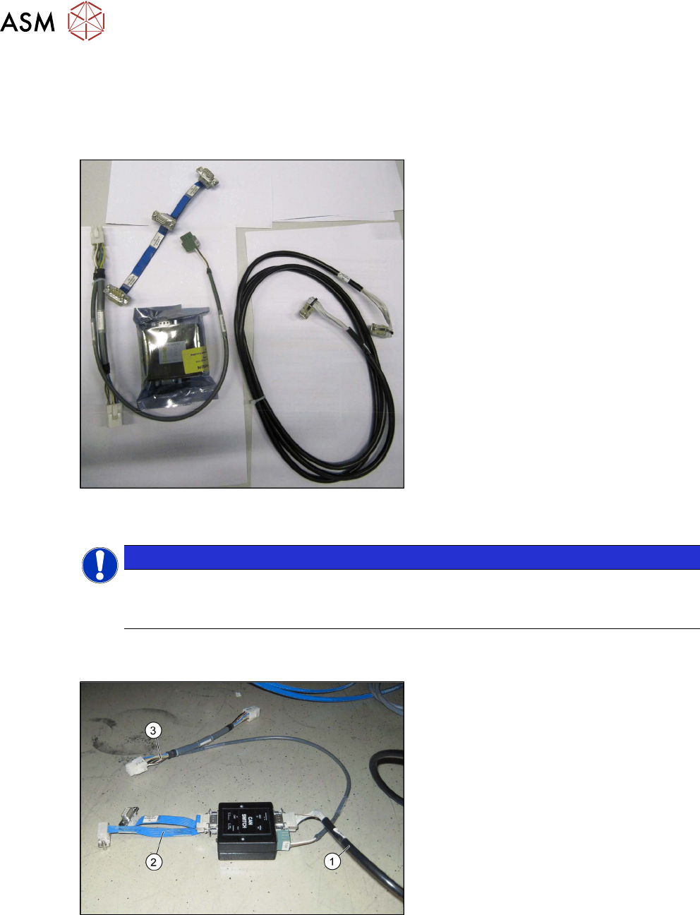
Fig.18: Upgrade kit COT-I 40 CAN switch for 2nd WPC
[03105017-xx]
●
Upgrade kit COT-I 40 CAN switch for
2nd WPC [03105017-xx]
NOTICE
Cable routing
► When running the cables, make sure there is enough play for easy fitting of the waste
tape slide later on.
► Set the DIP switches on the CAN- switch. See also the chapter 5.1.1 "Setting the DIP Switch
on the CAN Switch" [}87].
Fig.19: Cable on CAN switch
► Connect the cable to the CAN switch.
●
Can bus WPC M2 [03112552-xx] (1)
●
Adapter cable [03105018-xx] (2)
●
Y cable [03105669-xx] to X3 (3)