00197501-02_AI_WPC_Umbau_X-Series_S_DE_EN.pdf - 第92页
Review 5 Appendix 5.2 Circuit Diagrams 92 Assembly Instructions / Montageanleitung SIPLACE WPC an SIPLACE X-Serie S SIPLACE WPC on SIPLACE X Series S 03/2020 5.2.1 Upgrade kit WPC M2 CAN switch X-Series S Fig.58: Upgrad…
Review
5 Appendix
5.2 Circuit Diagrams
Assembly Instructions / Montageanleitung SIPLACE WPC an SIPLACE X-Serie S SIPLACE WPC on SIPLACE X
Series S 03/2020
91
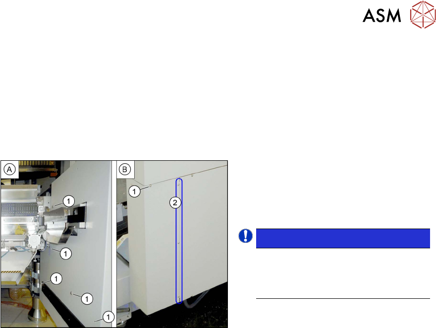
5.1.4 Dismantling the Lower Side Cover
Most tasks require that you dismantle the lower side cover from the location. This is shown below
using the example of location 2. The procedure for other locations is identical. The procedure is the
same for other locations.
Parts, equipment and tools
●
Shortened Allen key, if required
Dismantling the side cover
Fig.57: Dismantling the lower side cover
► While unscrewing, always hold on to
the side cover, to prevent it falling off.
► Remove the six screws(1) fastening
the inner(A)
and outer side(B) of the
side panel.
NOTICE!
The three fastening screws (2) on the
outer side are loosened as a default.
The side cover can be pulled out here.
.
► Remove the side cover.
Fitting the side cover
► Assembly is performed by following the above instructions in the reverse order.
5.2 Circuit Diagrams
For more information, refer to the circuit diagrams folder:
●
Detailed circuit diagrams folder for SIPLACE X-Series S (up to Gxxxx) [DE+EN:00197021‑xx]
●
Detailed circuit diagrams folder for SIPLACE X-Series S (from Hxxxx) [DE+EN:00197920‑xx]
Review
5 Appendix
5.2 Circuit Diagrams
92 Assembly Instructions / Montageanleitung SIPLACE WPC an SIPLACE X-Serie S SIPLACE WPC on SIPLACE X
Series S 03/2020
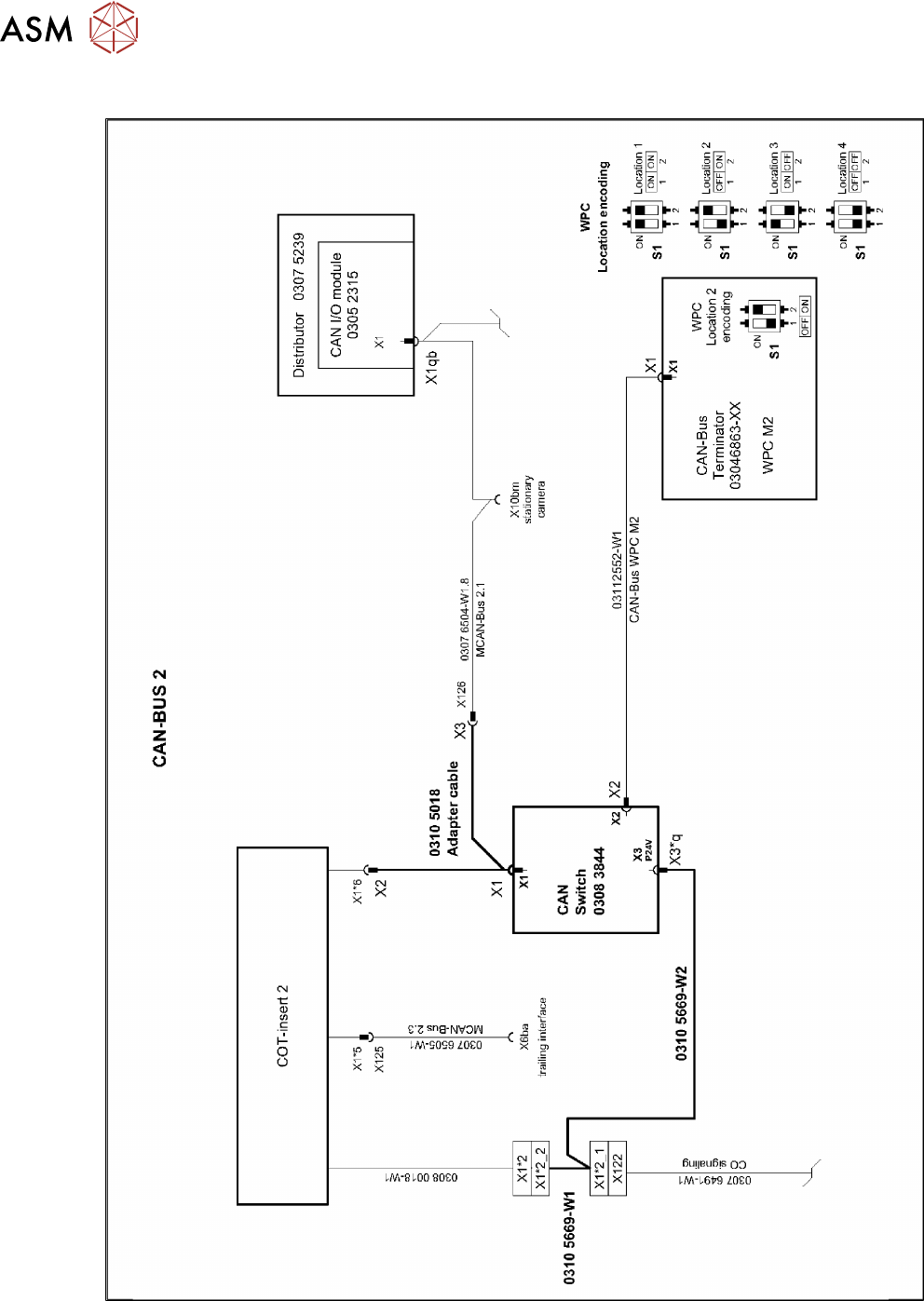
5.2.1 Upgrade kit WPC M2 CAN switch X-Series S
Fig.58: Upgrade kit WPC M2 CAN switch X-Series S
Review