00197501-02_AI_WPC_Umbau_X-Series_S_DE_EN.pdf - 第74页
Review 3 Setting up and Commissioning 3.3 Fitting the CAN Switch 74 Assembly Instructions / Montageanleitung SIPLACE WPC an SIPLACE X-Serie S SIPLACE WPC on SIPLACE X Series S 03/2020 Fig.23: Power supply on the X121 ► …
Review
3 Setting up and Commissioning
3.3 Fitting the CAN Switch
Assembly Instructions / Montageanleitung SIPLACE WPC an SIPLACE X-Serie S SIPLACE WPC on SIPLACE X
Series S 03/2020
73
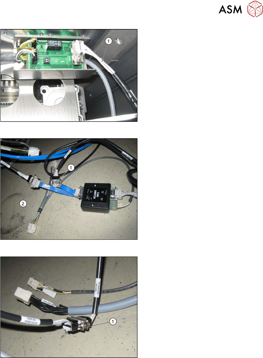
Fig.20: CAN bus on X1
► Fix the CAN bus cable [03112552-xx]
(1)
for the CAN bus X1 on the CAN bus
terminator.
Fig.21: Connection for cable [03105018-xx]
► Connect the cable [03105018-xx] from
X1 on the CAN switch to X3 (X1*6) on
the COT insert (2)
.
► Connect the cable [03105018-xx] from
X1 on the CAN switch to X2 (X126) (1)
.
Fig.22: COT insert on X125
► Connect the COT insert from X1*5 to
X125 (1)
.
Review
3 Setting up and Commissioning
3.3 Fitting the CAN Switch
74 Assembly Instructions / Montageanleitung SIPLACE WPC an SIPLACE X-Serie S SIPLACE WPC on SIPLACE X
Series S 03/2020
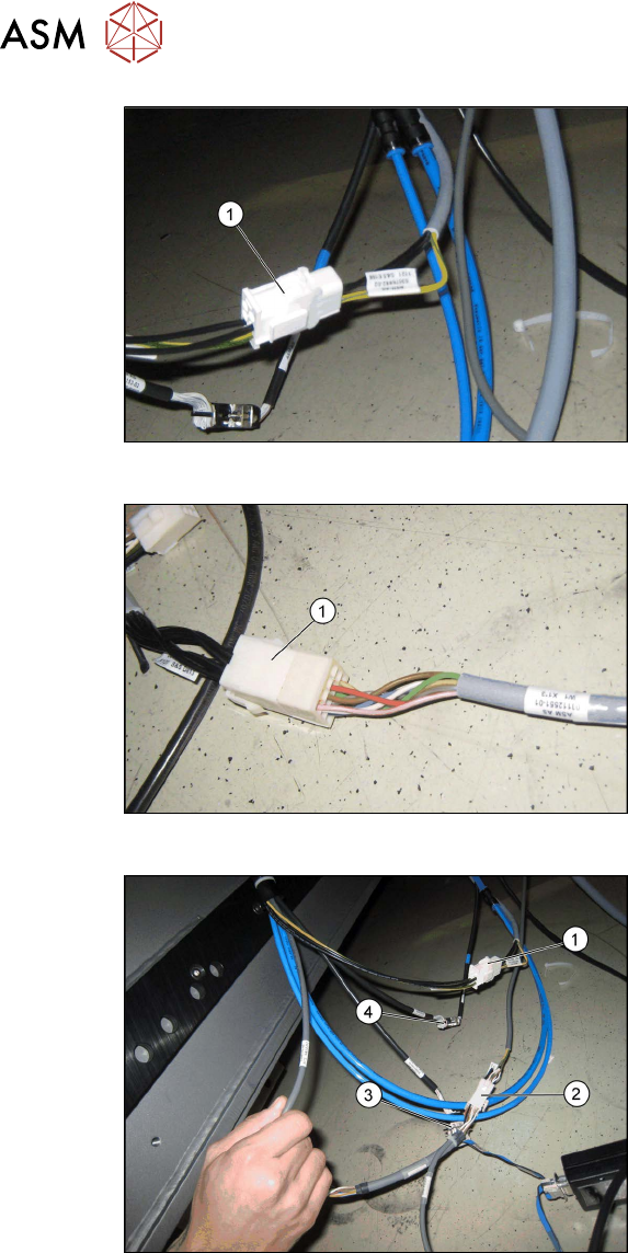
Fig.23: Power supply on the X121
► Connect the power supply X1*1 to
X121 (1)
.
Fig.24: Signaling circuit X123 on X1*3
► Connect the safety circuit and the sig-
naling circuit X123 to X1*3 [03112551-
xx] (1)
.
Fig.25: Intermediate connector on CAN switch
1. Power supply X1*1 on X121
2. X122 on X1*2
3. X3 to X1*6
4. X125 on X1*5
► Connect the intermediate connector
X122 to the power supply on the CAN
switch with X1*2 on the COT insert (2)
.
Review
3 Setting up and Commissioning
3.3 Fitting the CAN Switch
Assembly Instructions / Montageanleitung SIPLACE WPC an SIPLACE X-Serie S SIPLACE WPC on SIPLACE X
Series S 03/2020
75
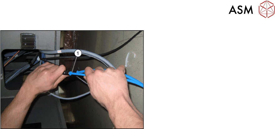
Fig.26: Pneumatic hoses on fixed table
► To do this, pull the unused pneumatic
hoses out of the machine.
► Remove the cover from the pneumatic
hoses.
► Connect the pneumatic hoses (1) for
the fixed table.
The X10bn connection remains open.
► Fix the cable into place with the cable ties so that nothing can be pinched or rubbed.