00197501-02_AI_WPC_Umbau_X-Series_S_DE_EN.pdf - 第73页
Review 3 Setting up and Commissioning 3.3 Fitting the CAN Switch Assembly Instructions / Montageanleitung SIPLACE WPC an SIPLACE X-Serie S SIPLACE WPC on SIPLACE X Series S 03/2020 73 Fig.20: CAN bus on X1 ► Fix the CAN…
Review
3 Setting up and Commissioning
3.3 Fitting the CAN Switch
72 Assembly Instructions / Montageanleitung SIPLACE WPC an SIPLACE X-Serie S SIPLACE WPC on SIPLACE X
Series S 03/2020
3.3 Fitting the CAN Switch
The CAN switch must be fitted for operating the SIPLACE WPC5/WPC6.
See also the attached information in the 5.2.1 "Upgrade kit WPC M2 CAN switch X-Series
S" [}92].
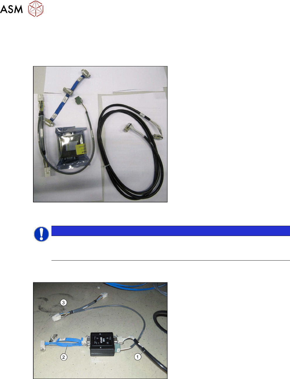
Fig.18: Upgrade kit COT-I 40 CAN switch for 2nd WPC
[03105017-xx]
●
Upgrade kit COT-I 40 CAN switch for
2nd WPC [03105017-xx]
NOTICE
Cable routing
► When running the cables, make sure there is enough play for easy fitting of the waste
tape slide later on.
► Set the DIP switches on the CAN- switch. See also the chapter 5.1.1 "Setting the DIP Switch
on the CAN Switch" [}87].
Fig.19: Cable on CAN switch
► Connect the cable to the CAN switch.
●
Can bus WPC M2 [03112552-xx] (1)
●
Adapter cable [03105018-xx] (2)
●
Y cable [03105669-xx] to X3 (3)
Review
3 Setting up and Commissioning
3.3 Fitting the CAN Switch
Assembly Instructions / Montageanleitung SIPLACE WPC an SIPLACE X-Serie S SIPLACE WPC on SIPLACE X
Series S 03/2020
73
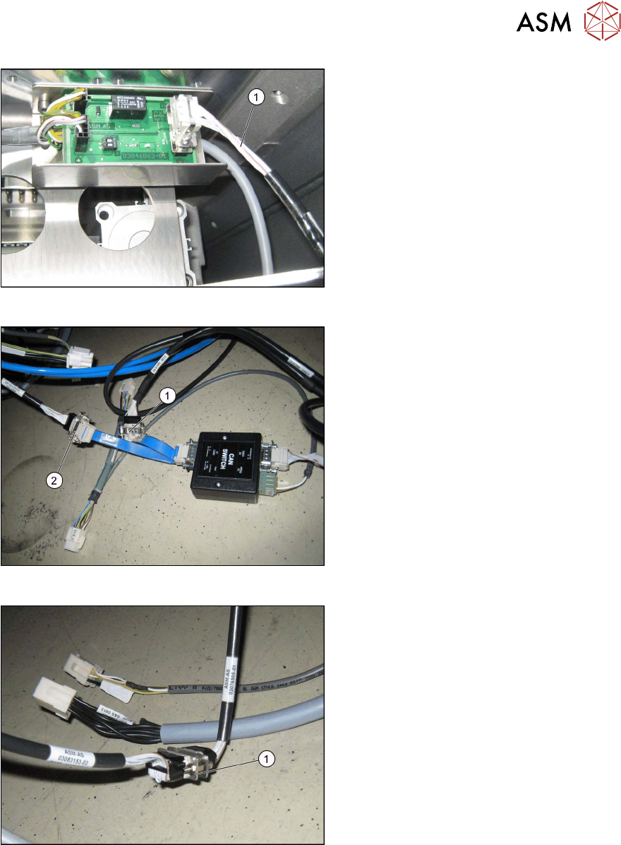
Fig.20: CAN bus on X1
► Fix the CAN bus cable [03112552-xx]
(1)
for the CAN bus X1 on the CAN bus
terminator.
Fig.21: Connection for cable [03105018-xx]
► Connect the cable [03105018-xx] from
X1 on the CAN switch to X3 (X1*6) on
the COT insert (2)
.
► Connect the cable [03105018-xx] from
X1 on the CAN switch to X2 (X126) (1)
.
Fig.22: COT insert on X125
► Connect the COT insert from X1*5 to
X125 (1)
.
Review
3 Setting up and Commissioning
3.3 Fitting the CAN Switch
74 Assembly Instructions / Montageanleitung SIPLACE WPC an SIPLACE X-Serie S SIPLACE WPC on SIPLACE X
Series S 03/2020
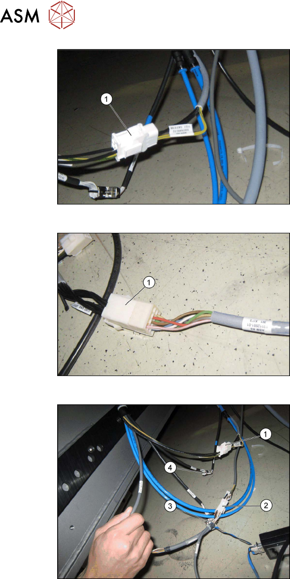
Fig.23: Power supply on the X121
► Connect the power supply X1*1 to
X121 (1)
.
Fig.24: Signaling circuit X123 on X1*3
► Connect the safety circuit and the sig-
naling circuit X123 to X1*3 [03112551-
xx] (1)
.
Fig.25: Intermediate connector on CAN switch
1. Power supply X1*1 on X121
2. X122 on X1*2
3. X3 to X1*6
4. X125 on X1*5
► Connect the intermediate connector
X122 to the power supply on the CAN
switch with X1*2 on the COT insert (2)
.