00192169-01.pdf - 第31页
Order No. 00192 169-01 User Manual - Productivity Lift E_SPLFS03_V40_11_0300_200300_V1_14.doc Last update: 20.03.2000 - Version V 1.14 Page 31 6.6 Max. time lift 2 If the ramp up mode setting is 1 to 0 , a PCP can be …
Order No. 00192 169-01 User Manual - Productivity Lift
E_SPLFS03_V40_11_0300_200300_V1_14.doc Last update: 20.03.2000 - Version V 1.14 Page 30
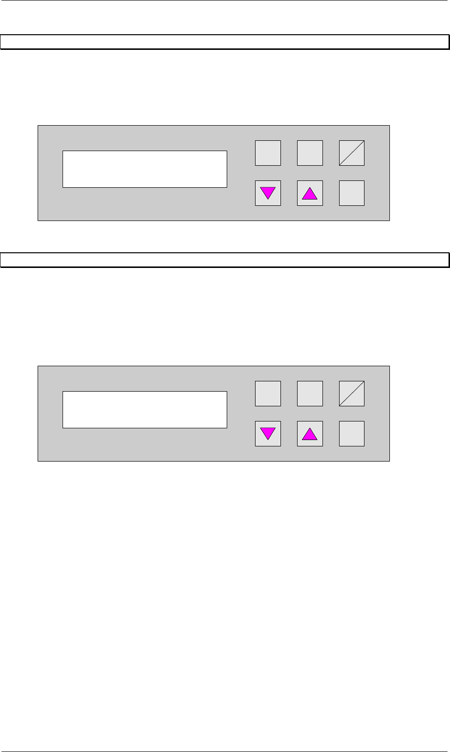
6.4 Wait period PCB
Time buffer for transferring a printed circuit board. Once this period has elapsed, the belt drive
is switched off and a fault indication is output since no PCB has arrived at the light barrier.
The unit of value is [0.01s] and the setting range is between 300 and 9999, which corresponds
to a time of 3 s to 99.99 s.
Hand
Stop
Start
Enter
Alt
Figure 26: Wait period PCB
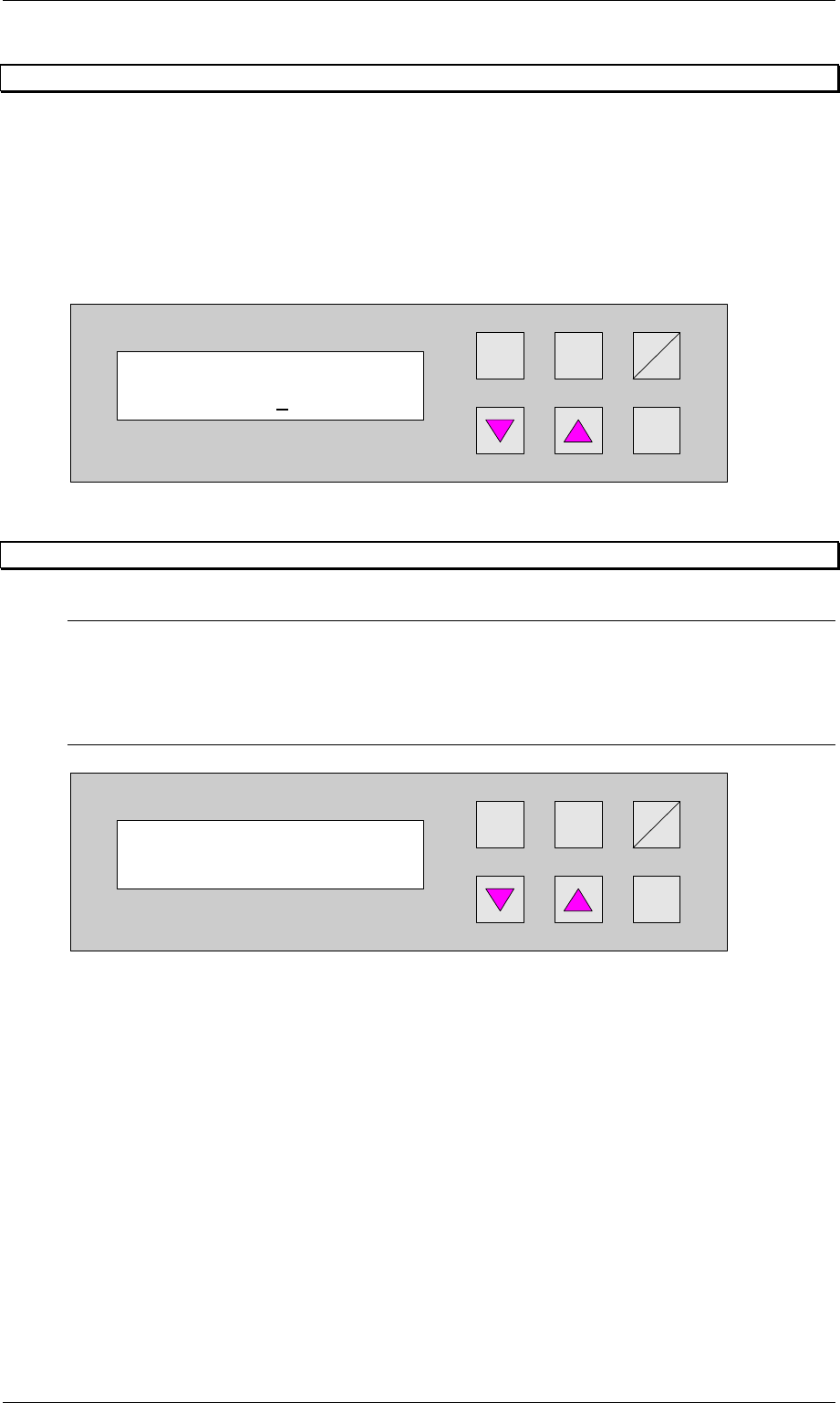
6.5 Max. time un-belt
If a PCB has not been transferred from the conveyor to the lift after the adjusted time, the
automatic operating mode is stopped and the error signal shows PCB annuated. The PCB is
only then transferred from the conveyor to the following lift when the error signal is confirmed
with the Enter cursor through the user.
The unit of the value is [s] and the adjustment area is 0s to 9999s, whereas the function is
switched off for the value 0s.
Hand
Stop
Start
Enter
Alt
Figure 27: Max. time un-belt
Wait period PCB
2000
Max. time un-belt
0
Order No. 00192 169-01 User Manual - Productivity Lift
E_SPLFS03_V40_11_0300_200300_V1_14.doc Last update: 20.03.2000 - Version V 1.14 Page 31
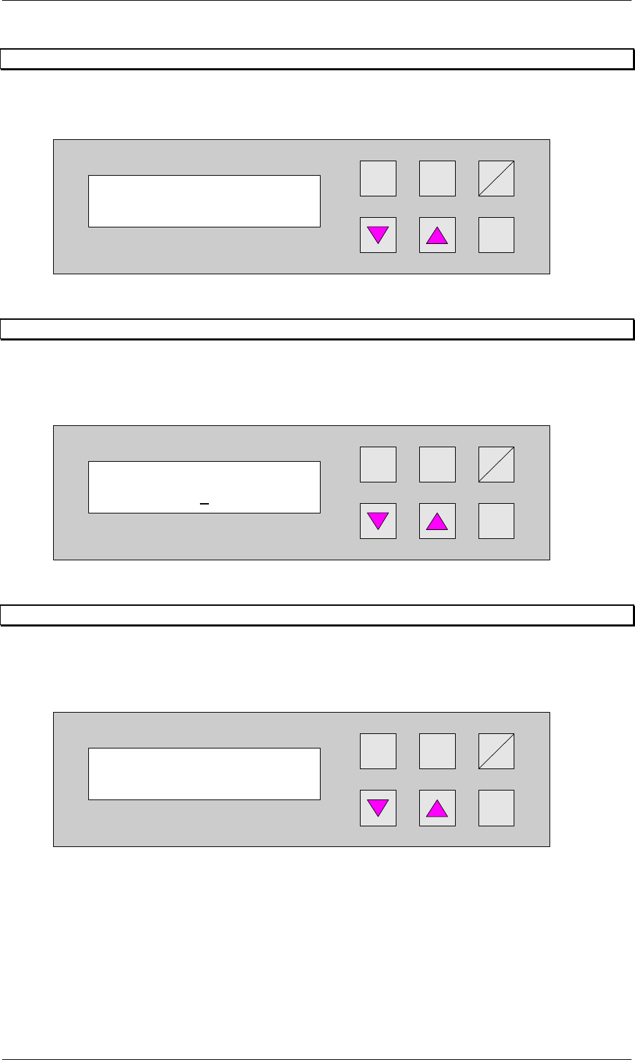
6.6 Max. time lift 2
If the ramp up mode setting is 1 to 0, a PCP can be buffered on track 3 until the transport on
track 1 or track 2 is available again. The selected time defines the waiting period. If the
selected time is exceeded, the PCP is transfered to the buffer on track 3 of the underfloor
conveyor . Depending on the availability of track 1 and 2 the PCP is transported reverse into
the Productivity Lift for further processing.
The dimension is in [s]. The setting range is between 0 600 s.
The feature is turned off by entering 0.
Hand
Stop
Start
Enter
Alt
Figure 28: Max. time lift 2
6.7 Code number
N.B.
All the settings after this menu affect the basic parameters of the device and are generally only
defined during initial installation. For this reason, access is protected by code number entry.
The code number requested in the configuration may only be known to one authorised person,
and may not be passed on to unauthorised persons.
Hand
Stop
Start
Enter
Alt
Figure 29: Code number
Code number
0000
Max. time Lift 2
000
Order No. 00192 169-01 User Manual - Productivity Lift
E_SPLFS03_V40_11_0300_200300_V1_14.doc Last update: 20.03.2000 - Version V 1.14 Page 32
6.8 Underneath belt
If the lift is installed as the end module in the line, it no longer has an underfloor conveyor.
This function must then be disabled in this menu.
Hand
Stop
Start
Enter
Alt
Figure 30: Underneath belt
6.9 Conveyors on LF1
Depending on the revision level of the Productivity Lift, the Top Conveyor, has one or two
conveyors. Select the appropriate setting 1 or 2. 1 for one conveyor. 2 for two
conveyors.
Hand
Stop
Start
Enter
Alt
Figure 31: Conveyors on LF1
6.10 ALT protection
With this function (adjustment switched on) the input possibilities in the configuration menu
(t and Alt cursor) and in the adjustment modus (Alt cursor) are locked. Input is only
possible when the interlock is used.
Hand
Stop
Start
Enter
Alt
Figure 32: ALT protection
Underneath belt
turned off
ALT protection
turned on
Conveyor on LF 1
1