00192169-01.pdf - 第35页
Order No. 00192 169-01 User Manual - Productivity Lift E_SPLFS03_V40_11_0300_200300_V1_14.doc Last update: 20.03.2000 - Version V 1.14 Page 35 6.14.1 Address width 1 Hand Stop Start Enter Alt Figure 36: Address width 1 6…
Order No. 00192 169-01 User Manual - Productivity Lift
E_SPLFS03_V40_11_0300_200300_V1_14.doc Last update: 20.03.2000 - Version V 1.14 Page 34
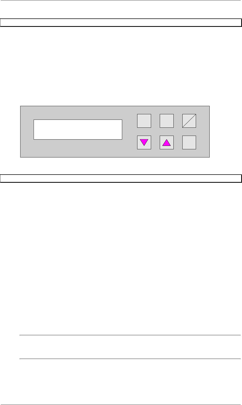
6.13 Lead adjusting 3
This menu has to be used to set the mode for operation of the automatic tracking facility for
width adjustment of the Underfloor Conveyor. The following are possible:
manual : The device has an electrical width adjustment facility but no automatic tracking
facility. The width must be adjusted in the manual-operating mode using the
corresponding function.
automatic : The device has an automatic tracking facility. This setting is then used to
constantly check the transport width of the device, which prescribes the width.
only at start : The device has an automatic tracking facility. This setting is then used to check
the transport width of the device, which prescribes the width, but only at the
start of the lift.
Hand
Stop
Start
Enter
Alt
Figure 35: Lead adjusting 3
6.14 Address width 1 / Address width 2 Option
This function is optional. It allows an automatic width adjustment of the Productivity Lifts within
a line configuration.
This menu is not active, if this option is available and Lead adjusting 1 and Lead adjusting 2
(chapter 6.11 and 6.12) has been set to manual.
The width setting of the Siplace Placement units is mandatory for the width setting of the
Productivity Lifts.
To enable the automatic width setting, there are certain line configuration settings required.
It is required, that there is a CAN-BUS featured module in front of the input module and a
Siplace placement unit behind the output module. The Siplace unit must be followed by a
CAN-BUS featured module.
The module before the input module (n-1) has address 1. This address is used to verify the
width. The module after the last placement machine (n+1) owns address 2. The requested
data from this module are used to set the width. The width of the Productivity Lifts in such a
line is changed only when all Siplace Placement units between input and output module carry
no PCB. The module (n+1) detects the new width setting at the last placement unit, using a
sensor. The new width setting is transmitted via CAN-BUS to the Productivity Lifts in the line.
Other settings are also possible e.g. module with address 1 is also addressed as module 2.
With this setting module (n-1) is used to verify and to transmit the width setting to the other
Productivity lifts.
The set up for this option must be performed by a qualified Service engineer.
NOTE
This setting has to be conducted by a Service engineer of the equipment manufacturer or
needs to be approved by Service engineer of the equipment manufacturer !
Lead adjusting 3
manual
Order No. 00192 169-01 User Manual - Productivity Lift
E_SPLFS03_V40_11_0300_200300_V1_14.doc Last update: 20.03.2000 - Version V 1.14 Page 35
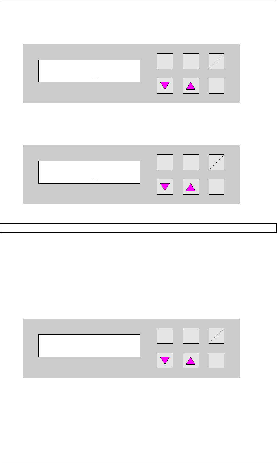
6.14.1 Address width 1
Hand
Stop
Start
Enter
Alt
Figure 36: Address width 1
6.14.2 Address width 2
Hand
Stop
Start
Enter
Alt
Figure 37: Address width 2
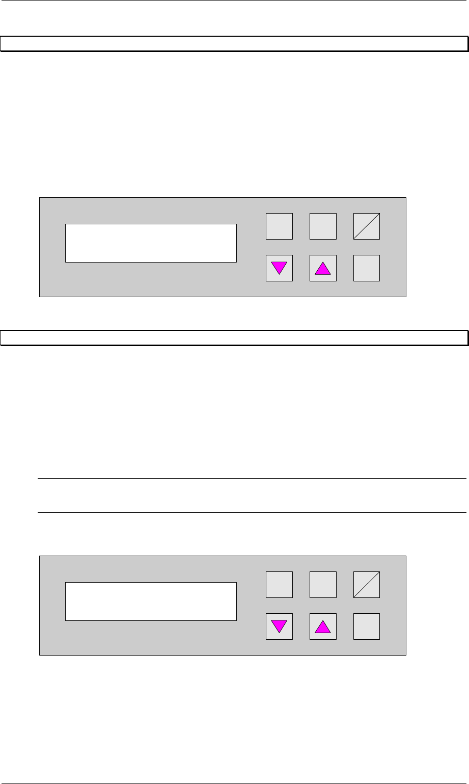
6.15 Reference width 1
This setting defines the reference width of the Top Conveyor.(only option). This setting allows
the matching of displayed width and actual width of the Top Conveyor transport.
By changing the setting the width is increased or decreased.
A typical value is between 0480 0490.
This menu item is only available, if the function Lead adjusting 1 is activated (chapter 6.11,
page 33).
The standard configuration is not equipped with an automatic width setting of the Top
Conveyor.
The lowest increment is [0.1mm].
Hand
Stop
Start
Enter
Alt
Figure 38: Reference width 1
Reference width 1
0500
Address width 1
0000
Address width 2
0000
Order No. 00192 169-01 User Manual - Productivity Lift
E_SPLFS03_V40_11_0300_200300_V1_14.doc Last update: 20.03.2000 - Version V 1.14 Page 36
6.16 Reference width 2
This setting defines the reference width of the Shuttle Conveyor. This setting allows the
matching of displayed width and actual width of the Shuttle Conveyor.
By changing the setting the width is increased or decreased.
A typical value is between 0480 0490.
This menu item is only available, if the function lead adjusting 1 is activated (chapter 6.12,
page 33).
The standard configuration is equipped with an automatic width setting of the Shuttle
Conveyor.
The unit of value is [0.1mm].
Hand
Stop
Start
Enter
Alt
Figure 39: Reference width 2
6.17 Reference width 3
This setting defines the reference width of the Underfloor Conveyor. This setting allows the
matching of displayed width and actual width of the Underfloor Conveyor.
By changing the setting the width is increased or decreased.
A typical value is between 0480 0490.
This menu item is only available, if the function lead adjusting 1 is activated (chapter 6.13,
page 34).
The standard configuration is equipped with an automatic width setting of the Underfloor
Conveyor.
Note
If the lift is implemented as an end module, this menu does not appear.
The unit of value is [0.1mm].
Hand
Stop
Start
Enter
Alt
Figure 40: Reference width 3
Reference width 3
0490
Reference width 2
0490