00192169-01.pdf - 第40页
Order No. 00192 169-01 User Manual - Productivity Lift E_SPLFS03_V40_11_0300_200300_V1_14.doc Last update: 20.03.2000 - Version V 1.14 Page 40 6.26 Start continuous mode 3 N.B. This continuous operation mode can only be …
Order No. 00192 169-01 User Manual - Productivity Lift
E_SPLFS03_V40_11_0300_200300_V1_14.doc Last update: 20.03.2000 - Version V 1.14 Page 39
6.24 Start continuous mode 1
This continuous operation mode can be implemented with two lift modules and one placement
machine. A PCB is transported on the upper transport level from the lift to the placement
machine, on to the next lift and, from there, back again to the front lift on the underfloor
conveyor. This cycle is repeated until the continuous operation mode is interrupted.
The continuous operation mode is initiated from this menu using the Hand key. The
Start/Stop key is used to interrupt it.
Hand
Stop
Start
Enter
Alt
Figure 47: Start continuous mode 1
6.25 Start continuous mode 2
This continuous mode can run with at least two or more lift modules and the according number
of conveyors. No placement systems are needed. A PCB is driven down by lift 1, transported
via the conveyor to lift 2, where it is moved first up and then down and transferred to the next
lift via a conveyor etc. This cycle repeats until the running mode is interrupted. After the last lift
an loading unit can be placed which puts the PCBs into magazines. The unloading of PCBs
into the first lift can be made by a input station.
The continuous operation mode is initiated from this menu using the Hand key. The
Start/Stop key is used to interrupt it.
Hand
Stop
Start
Enter
Alt
Figure 48: Start continuous mode 2
Start continuous
mode 1?
Start continuous
mode 2?
Order No. 00192 169-01 User Manual - Productivity Lift
E_SPLFS03_V40_11_0300_200300_V1_14.doc Last update: 20.03.2000 - Version V 1.14 Page 40
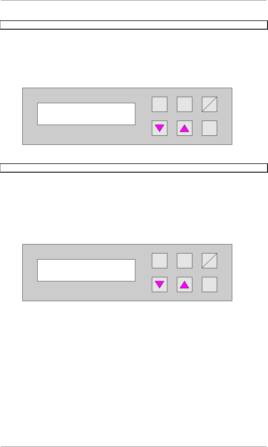
6.26 Start continuous mode 3
N.B.
This continuous operation mode can only be implemented by the manufacturer using special
test equipment. An attempt by a user to initiate this continuous operation mode produces an
error message.
Hand
Stop
Start
Enter
Alt
Figure 49: Start continuous mode 3
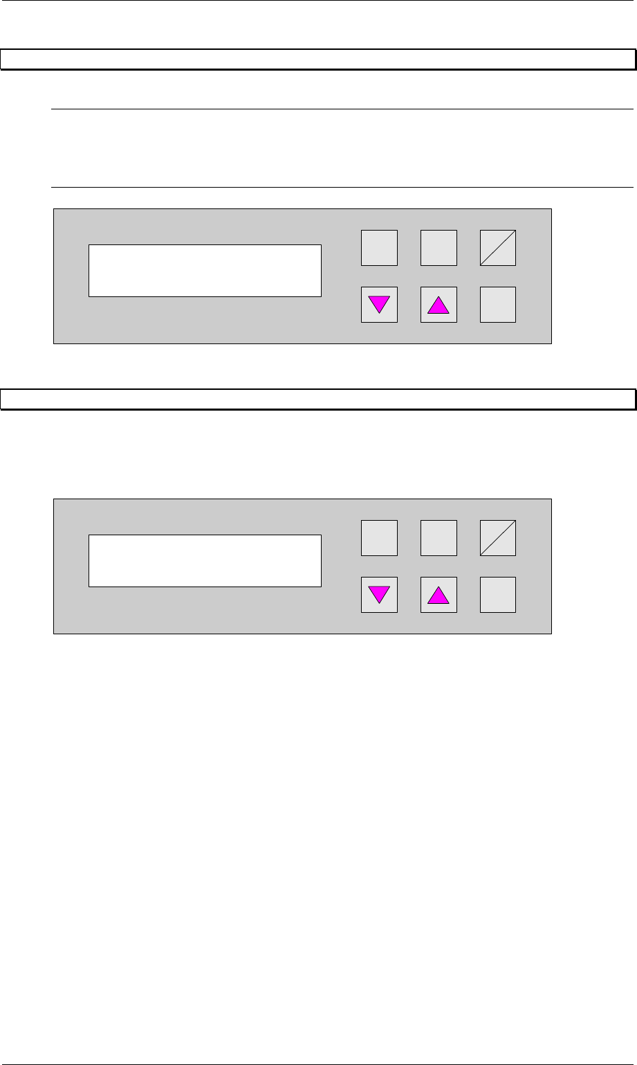
6.27 Input ident number
This feature enables the input of an identification number. The identification number allows to
define a variation of machine parameters for a specific PCB. This menu item allows to switch
on / off this function. The input has to be done in the set-up mode (section 7.1, page 41)
Hand
Stop
Start
Enter
Alt
Figure 50: Input ident number
Start continuous
mode 3?
Input ident no.
Turned off
Order No. 00192 169-01 User Manual - Productivity Lift
E_SPLFS03_V40_11_0300_200300_V1_14.doc Last update: 20.03.2000 - Version V 1.14 Page 41
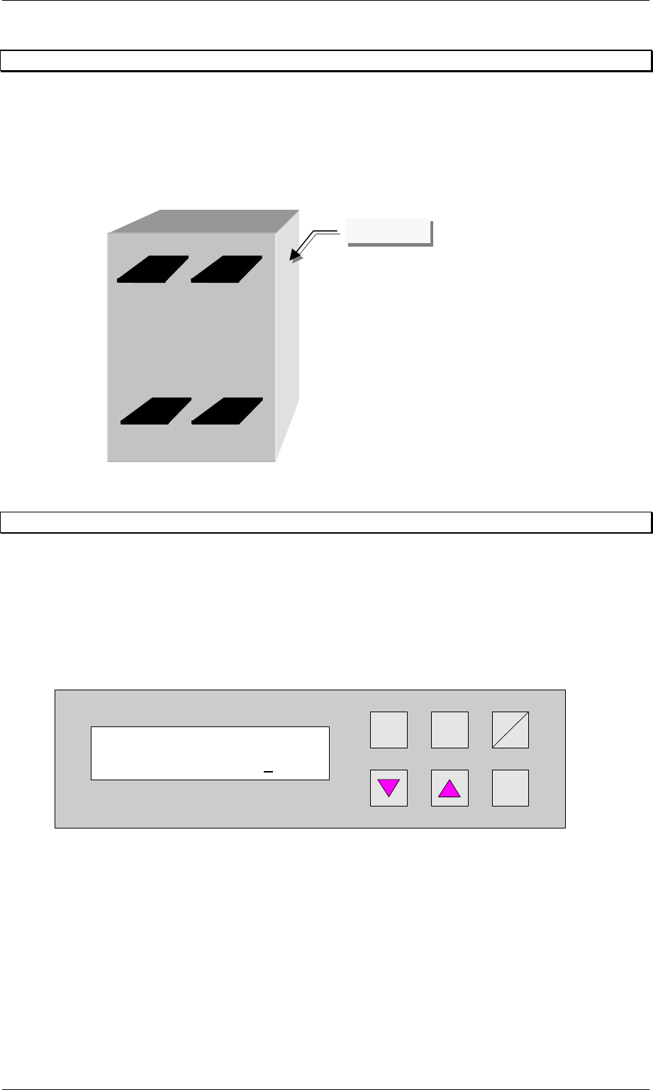
7 Set-up mode
In set-up mode, it is possible to enter and modify parameters that do not serve the basic
setting of the system, but that, for example, show the values dependent on the size of the
machine type. Press the Alt key to access the set-up mode menu.
Definition:
View of the direction of transit.
Figure 51: Definition / schematic of the transport tracks
7.1 Ident number
This selection can be used to assign an identification number to the following set of
parameters. When starting the system, only the corresponding PCB number need be called
up, and the system sets the stored parameters automatically. The number consists of two
assignment digits and one eight-digit identification. The assignment digits can be used to call
up the parameter set when starting the system. The eight-digit identification can be changed at
random and only serves the input of user-specific identification numbers. Each number has
only one numerical entry.
Hand
Stop
Start
Enter
Alt
Figure 52: Ident number
Ident number
01 00000001
Track 1Track 2
Track 3Track 4
Operator side