00192169-01.pdf - 第37页
Order No. 00192 169-01 User Manual - Productivity Lift E_SPLFS03_V40_11_0300_200300_V1_14.doc Last update: 20.03.2000 - Version V 1.14 Page 37 6.18 Max. width board Here the maximum transport width permissible for the sy…
Order No. 00192 169-01 User Manual - Productivity Lift
E_SPLFS03_V40_11_0300_200300_V1_14.doc Last update: 20.03.2000 - Version V 1.14 Page 36
6.16 Reference width 2
This setting defines the reference width of the Shuttle Conveyor. This setting allows the
matching of displayed width and actual width of the Shuttle Conveyor.
By changing the setting the width is increased or decreased.
A typical value is between 0480 0490.
This menu item is only available, if the function lead adjusting 1 is activated (chapter 6.12,
page 33).
The standard configuration is equipped with an automatic width setting of the Shuttle
Conveyor.
The unit of value is [0.1mm].
Hand
Stop
Start
Enter
Alt
Figure 39: Reference width 2
6.17 Reference width 3
This setting defines the reference width of the Underfloor Conveyor. This setting allows the
matching of displayed width and actual width of the Underfloor Conveyor.
By changing the setting the width is increased or decreased.
A typical value is between 0480 0490.
This menu item is only available, if the function lead adjusting 1 is activated (chapter 6.13,
page 34).
The standard configuration is equipped with an automatic width setting of the Underfloor
Conveyor.
Note
If the lift is implemented as an end module, this menu does not appear.
The unit of value is [0.1mm].
Hand
Stop
Start
Enter
Alt
Figure 40: Reference width 3
Reference width 3
0490
Reference width 2
0490
Order No. 00192 169-01 User Manual - Productivity Lift
E_SPLFS03_V40_11_0300_200300_V1_14.doc Last update: 20.03.2000 - Version V 1.14 Page 37
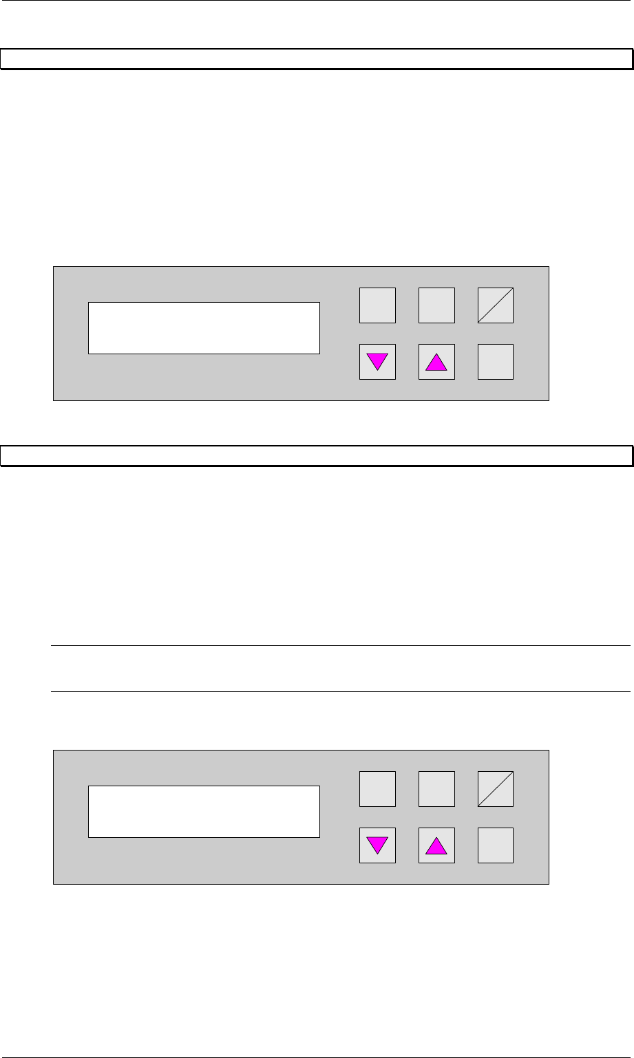
6.18 Max. width board
Here the maximum transport width permissible for the system is set. The unit of value is
[0.1mm]. The setting range is between 500 and 2160, which corresponds to a width of 50mm
to 216mm.
Hand
Stop
Start
Enter
Alt
Figure 41: Max. width board
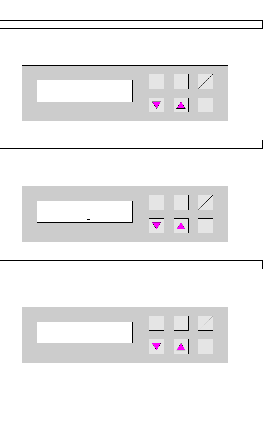
6.19 Start speed down
The speed at which the lower lift starts up when travelling downwards and which is reverted to
by braking just before reaching the final position.
The setting is a percentage of the motor rating. The value should be between 23% and 27% .
Hand
Stop
Start
Enter
Alt
Figure 42: Start speed down
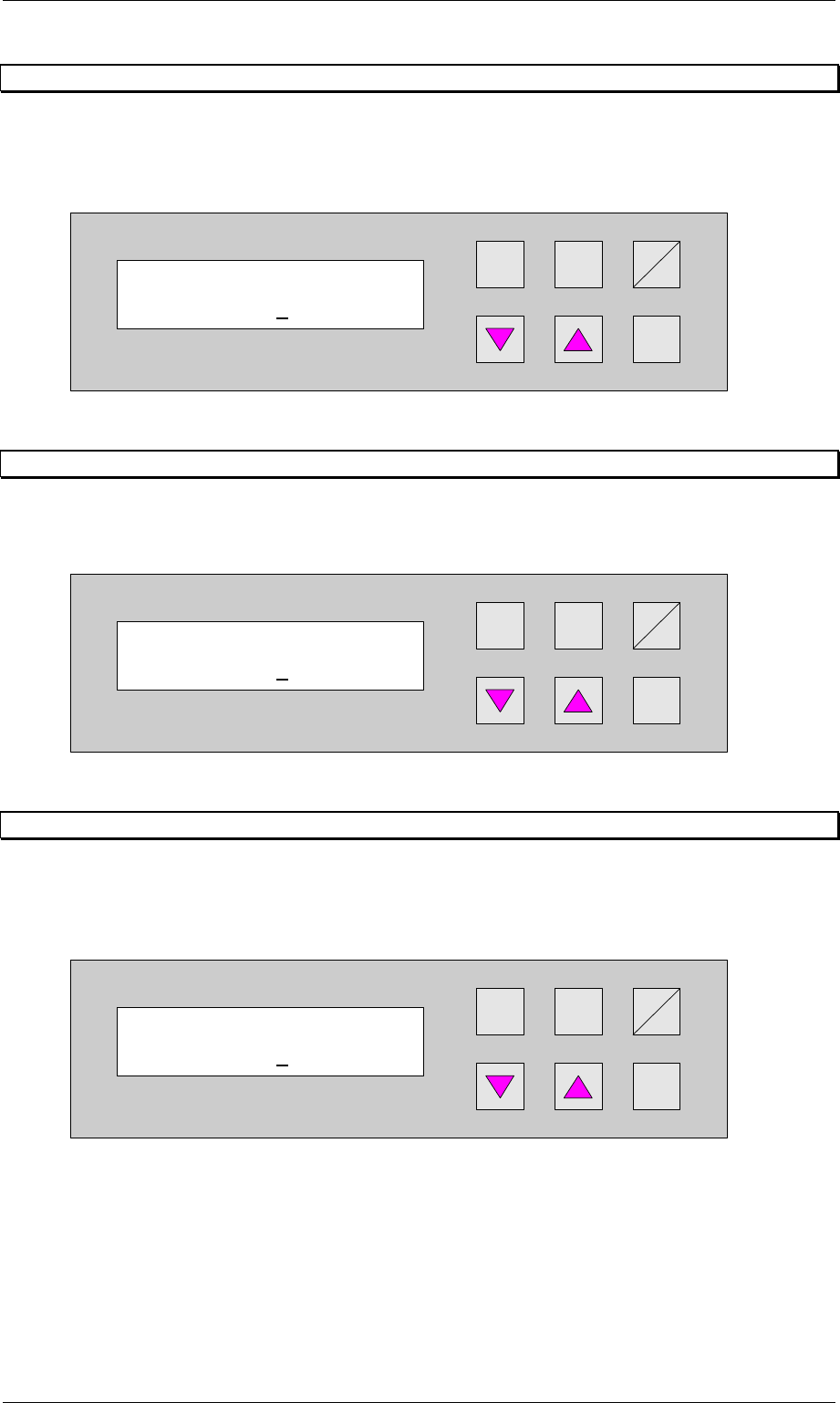
6.20 Start speed up
The speed at which the lower lift starts up when travelling upwards and which is reverted to by
braking just before reaching the final position.
The setting is a percentage of the motor rating. The value should be between 20% and 25% .
Hand
Stop
Start
Enter
Alt
Figure 43: Start speed up
Start speed down
025
Start speed up
023
Max. width board
2160
Order No. 00192 169-01 User Manual - Productivity Lift
E_SPLFS03_V40_11_0300_200300_V1_14.doc Last update: 20.03.2000 - Version V 1.14 Page 38
6.21 Travelling speed
The speed at which the lower lift travels between the two final positions. The value to be
entered is a percentage value of the entire motor output.
The setting is a percentage of the motor rating. The value should be between 60% and 80% .
Hand
Stop
Start
Enter
Alt
Figure 44: Travelling speed
6.22 Run out time down
A time that can be set to secure the positioning of the lower lift in its final lower position. This
guarantees that the lift has reached its final position before a PCB is transferred or delivered.
The unit of value is [0.01s]. The value should be between 001 and 003.
Hand
Stop
Start
Enter
Alt
Figure 45: Run out time down
6.23 Run out time up
A time that can be set to secure the positioning of the lower lift in its final upper position. This
guarantees that the lift has reached its final position before a PCB is transferred or delivered.
The unit of value is [0.01s]. The value should be between 005 and 008.
Hand
Stop
Start
Enter
Alt
Figure 46: Run out time up
Travelling speed
080
Run out time down
002
Run out time up
007