00192169-01.pdf - 第53页
Order No. 00192 169-01 User Manual - Productivity Lift E_SPLFS03_V40_11_0300_200300_V1_14.doc Last update: 20.03.2000 - Version V 1.14 Page 53 Machine type: input module, cluster module, cross module Length L1 540 mm Wid…
Order No. 00192 169-01 User Manual - Productivity Lift
E_SPLFS03_V40_11_0300_200300_V1_14.doc Last update: 20.03.2000 - Version V 1.14 Page 52
9.2 Automatic tracking via CAN bus
The lift is connected to other systems via a CAN bus. The data for the current width are
transferred via this CAN bus. The configuration of the lift determines which system is
responsible for the width and how the width is queried and checked.
Communication via CAN bus is only possible with our systems.
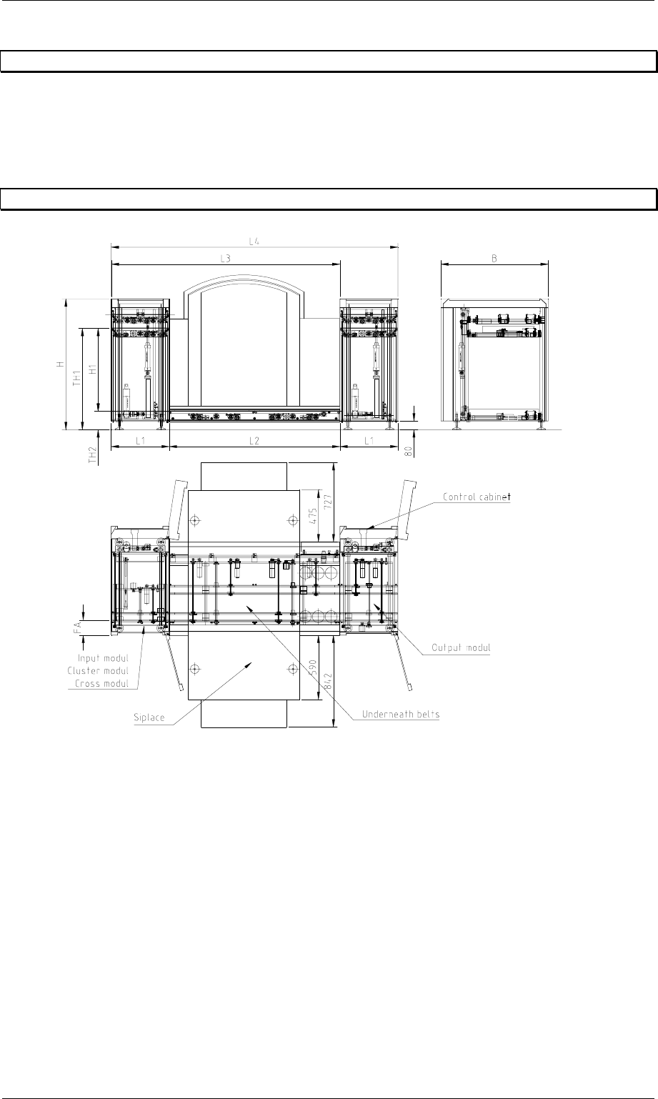
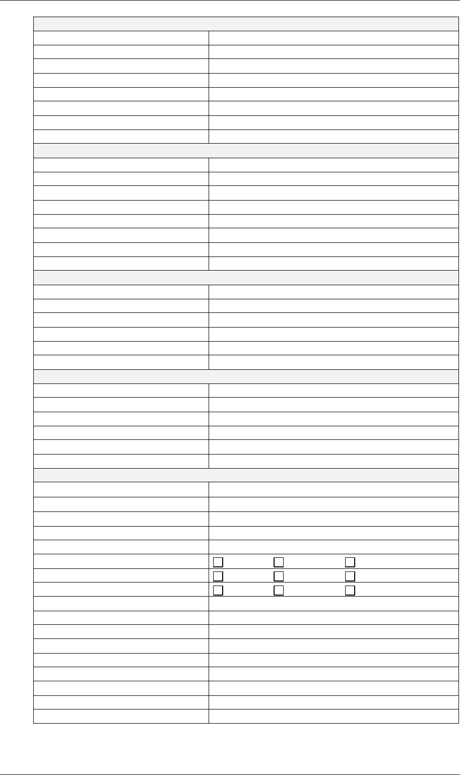
10 Technical Data
Figure 72: Technical Data
Installation and operation instructions
For the installation and operation of the productivity lift the following advice have to be
observed:
1. Area load allowed for undercover 0,2 t/m²
2. room temperature 15°C until 35°C
3. humidity in the area 30% until 70%
4. average humidity ≥ 45%
Order No. 00192 169-01 User Manual - Productivity Lift
E_SPLFS03_V40_11_0300_200300_V1_14.doc Last update: 20.03.2000 - Version V 1.14 Page 53
Machine type: input module, cluster module, cross module
Length L1 540 mm
Width B 1045 mm
Height H 1200 mm with TH1 930 mm
Shuttle H1 760 mm
Weight 212 kg
Width adjustment Shuttle with stepper motor
Width adjustment Top conveyor manual
Machine type: output module
Length - lift L1 540 mm
Width B 1045 mm
Height H 1200 mm with TH1 930 mm
Shuttle H1 760 mm
Weight 212 kg
Width adjustment Shuttle with stepper motor
Width adjustment Top conveyor manual
Underfloor conveyor for Siplace short for S20
Length lower belt L2 1595 mm
Total module length L3 2135 mm
Total unit length L4 2675 mm
Weight 90 kg
Width adjustment with stepper motor
Underfloor conveyor for Siplace long for HS50
Length lower belt L2 2385 mm
Total module length L3 2925 mm
Total unit length L4 3465 mm
Weight 120 kg
Width adjustment with stepper motor
All machine types
Transport height - above TH1
930 mm ± 30 mm
Transport height - below TH2
170 mm ± 30 mm
PCB width 50 - 217 mm
PCB length 50 - 460 mm
PCB edging during transport 3mm
Interface inlet ... Siemens SMEMA
Interface outlet ... Siemens SMEMA
Automatic tracking none at inlet at outlet
Electrical connection 230V / 50Hz or 110V / 60Hz AC
Power input 0,4 kW
Secondary voltage 24V DC
Fuse-protection 1x 6,3A
Compressed air supply 5 bar and 10 l/min
Controller CAN/MM100 and CAN/MS1
Operation via control desk CAN/P50
Programme version V 40.11
Order No. 00192 169-01 User Manual - Productivity Lift
E_SPLFS03_V40_11_0300_200300_V1_14.doc Last update: 20.03.2000 - Version V 1.14 Page 54
11 Description of interface
An interface is required between adjoining machines for take-over or hand-over processes.
Our machines can be equipped with different interfaces. A change of interface always requires
the connection of suitable connecting facilities. Interface modifications without connecting the
right connecting facilities may result in a functional error and possibly cause an electrical fault.
We would be glad to provide you with information regarding difficult aspects of modifying
interfaces.
1. When the machine is equipped with interface as the Siemens Definition describes, a 37-
pin AMP plug and socket are used for the connection (refer to Siemens).
2. When the machine is equipped with interface as the SMEMA Definition describes, refer to
SMEMA.
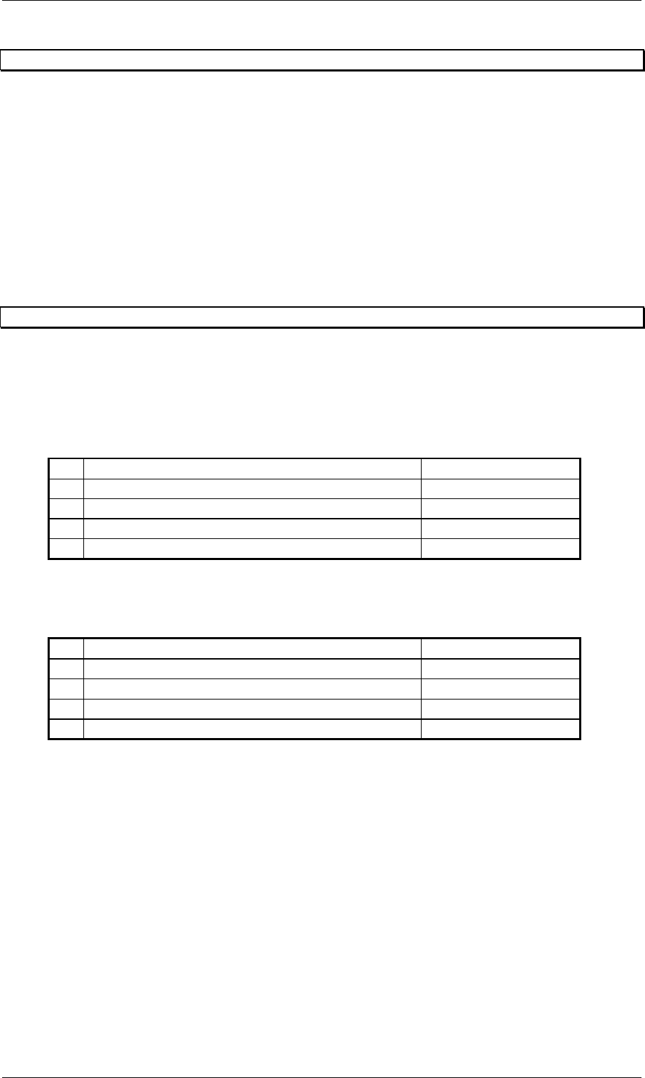
11.1 SMEMA interface definition
When the machine is equipped with interface as the SMEMA Definition describes, a 14-pin
AMP plug and socket are used for the connection.
SMEMA interface definition releases at the signal potential free contact.
11.1.1 Inlet side
Pin Signal description
1 24V from machine n-1
2 Output relay contact Ready to machine n-1
3 24V from ASYS machine
4 Prompt loop input 21 of machine n-1
11.1.2 Outlet side
Pin Signal description
1 24V from ASYS machine
2 Ready loop input 23 of machine n-1 Switched Pin 1
3 24 V from machine n+1
4 Output relay contact Prompt to machine n+1